
Joined October 2011
- Tweets 25,113
- Following 442
- Followers 3,081
- Likes 163,003
2,681 Photos and videos


Pinned Tweet

The window of opportunity is rapidly closing in which we can build the things that are going to get us through the coming crisis.
We must build our capabilities offline now, whilst they can still be coordinated online to furnish us with the necessary resources to get us through.
3
7
55
5,807
Alex - That Steam Guy retweeted

Our volunteers are hard at work repointing and lime washing castle walls at Sorbie Tower!
3
7
80
890
Alex - That Steam Guy retweeted

Because in the end, the future will not be shaped by what we build fast, but by what we build to last. Let us begin where all great things begin. Let us begin with the foundations.
Join us this August at the Witan!

2
7
24
1,421
Alex - That Steam Guy retweeted

16h
If I was a Russian intelligence operation tasked with subverting Britain I would feel more redundant than the man who fits indicators to BMWs.
10
20
180
2,726
I said at the back end of last year that the numbers would tern negative.
Most of this is actually because the Home Office counts expired visas as emigration but, the fact remains that the mass migration phase is over.
The coming integration phase will be infinitely worse.


2
1
30
983
The Government is literally writing cheques the Treasury can't cash.
@NomosEvents in his excellent interview with AA (late of this Parish) was right to highlight the non-technical nature of our Elites.
They refuse to accept that Hard Power is very expensive in money & resources

Rich Knighton, CDS freely saying to a House of Lord Committee that the DIP settlement that @JohnHealey_MP resigned over does not provide enough RDEL budget (day-to-day running expenses) for defence - operations and training will have to be cut.
If this is imposed, a resignation matter for Knighton and @DanJarvisMBE ?

1
4
18
806
Alex - That Steam Guy retweeted
NEW, from Academic Agent & Scrump
A Defence Shambles
youtu.be/JgOUCt3Du00?is=1pNy…
3
7
33
1,419
Alex - That Steam Guy retweeted

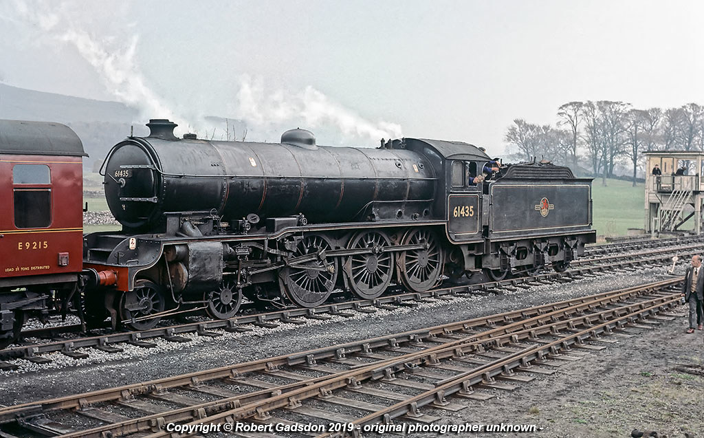
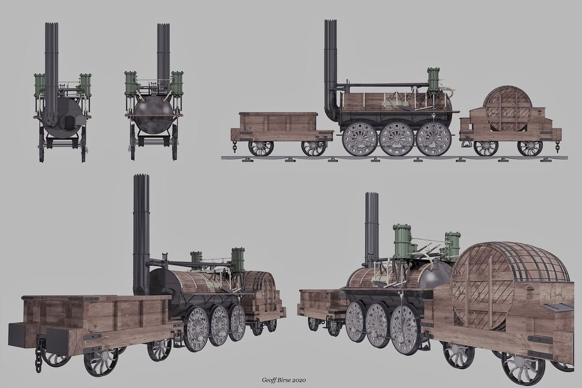
A Very Technical Kettle - Loco Boiler Design Over the Years.
The development of the steam locomotive boiler in Britain traces a path from rudimentary pressure vessels to sophisticated, highly engineered components that powered the nation’s railways for well over a century.
What began as little more than a dangerous cylindrical “kettle” evolved through careful refinement of materials, construction techniques, and safety systems, shaped by the demands of main-line service and hard lessons from occasional catastrophic failures.
Richard Trevithick’s pioneering work in the early 1800s marked the shift to practical high-pressure steam on rails. His 1804 Pen-y-Darren locomotive featured a compact wrought-iron boiler with a single large internal flue running through the water space, essentially a Cornish-type boiler adapted for mobility. Operating at pressures around 50–60 psi, which was far higher than the low-pressure atmospheric engines of Newcomen and Watt. This design integrated the cylinder closely with the boiler to minimise heat loss. The fire burned inside the flue, with hot gases passing once through the water before exhausting up the chimney. While revolutionary, these early boilers used relatively thick but rudimentary wrought-iron plates joined by basic riveting, with minimal staying and no sophisticated water-level indication. They were prone to sudden failure if the fire was allowed to burn unchecked or if pressure built excessively, as the materials lacked the uniformity of later steels.
The decisive advance came with George and Robert Stephenson’s Rocket of 1829, which won the Rainhill Trials and established the multi-tubular fire-tube boiler as the British, and soon worldwide standard. The boiler barrel was a cylindrical shell, roughly 3 ft 4 in diameter by 6 ft long and formed from ¼-inch wrought-iron plates, closed at each end by tubeplates. Instead of a single large flue, it incorporated 25 small-diameter copper fire-tubes running through the water space from the firebox to the smokebox. This dramatically increased the heating surface area—roughly 17 sq ft from the firebox itself and 138 sq ft from the tubes—allowing far more rapid steam generation from a compact package. The firebox was of copper sheet (sides and crown) with a somewhat rectangular form, creating a water-jacketed space around the fire; copper was chosen for its excellent thermal conductivity and resistance to corrosion. Exhaust steam was directed up the chimney via a blastpipe, creating induced draught through the fire and tubes. Working pressure was around 50 psi, and the whole assembly sat on a simple frame with the cylinders mounted at an angle. This design balanced efficiency, weight, and reliability in a way that earlier single-flue boilers could not match.
Throughout the mid-19th century, British locomotive boilers grew larger and more sophisticated as traffic demands increased. The cylindrical barrel was extended and strengthened with multiple courses of riveted plates, typically using lap or butt joints. The inner firebox, almost invariably of copper in British practice, sat within an outer wrapper plate, forming narrow water legs around the sides and a larger water space above the crown sheet. The crown sheet itself was supported by a forest of stays: early designs used girder stays or longitudinal bars, later supplemented or replaced by numerous radial or vertical staybolts screwed or riveted through both inner and outer plates. A foundation ring or mud ring at the base sealed the water space and collected sediment. Tubeplates were thick copper or wrought iron, with the small fire-tubes (and later larger superheater flues) expanded and beaded or ferruled into place. The smokebox at the front collected ash and directed gases to the chimney, while the ashpan below the grate controlled airflow with dampers. Materials evolved alongside construction: wrought iron, produced by puddling and relatively tolerant of minor defects, gave way from the 1860s onward to mild steel plates made by the Bessemer or Siemens-Martin processes, offering greater strength and consistency for higher pressures. Copper fireboxes remained the British norm for decades because of their superior heat transfer and longevity in service, despite the higher initial cost; steel fireboxes were tried experimentally but often suffered from scaling or cracking unless water treatment was meticulous.
As boilers became larger and pressures climbed toward 150–200 psi by the late Victorian era, the risks became painfully apparent. British records document numerous explosions between the 1810s and mid-20th century, with Hewison noting 137 land-based cases up to 1962, a proportion involving locomotives. Early incidents on the Stockton & Darlington Railway in 1828 highlighted the dangers of inadequate pressure control on pioneering engines. Later examples included the 1862 explosion of the broad-gauge GWR locomotive Perseus at Westbourne Park shed, attributed to low water combined with excessive pressure after washing out, and the 1909 Rhymney Railway incident at Cardiff Docks where an inoperative safety valve allowed catastrophic over-pressurisation, killing three. Firebox collapses were particularly common when water levels dropped below the crown sheet, exposing it to direct flame; the sudden generation of steam from residual water could tear the boiler apart. Barrel failures, though rarer later on, occurred when safety valves were mis-set or tampered with, as in the 1909 Cardiff and 1921 Buxton cases.
These tragedies drove systematic improvements in British railway practice. Safety valves evolved from simple lever-weighted types (easily overloaded or tied down) to more reliable spring-loaded and eventually “pop” designs that lifted cleanly and audibly. Fusible plugs, low-melting-point alloy inserts in the crown sheet, became standard; if the crown overheated, the plug melted and released steam to douse the fire. Accurate water gauges (initially try-cocks, later glass tubes protected by guards) and pressure gauges with siphon loops allowed crews to monitor conditions closely. Construction standards tightened: double-riveted or butt-strapped seams reduced grooving and leakage, while regular hydraulic testing, to 1½ times working pressure, and periodic examinations by competent inspectors became mandatory under railway company rules and later Board of Trade oversight. Water treatment improved to combat scaling and corrosion, and operating procedures emphasised maintaining water levels and never leaving the boiler unattended.
By the early 20th century, further refinements appeared in British designs. Superheaters, which were typically multiple elements inside larger flues, raised steam temperature for drier, more efficient expansion in the cylinders. Belpaire fireboxes with flat crowns and squared sides improved staying and steam space. Larger locomotives featured extensive radial staying and, in some cases, thermic syphons or arch tubes to promote water circulation. Pressures rose to 225–250 psi in express passenger engines, with the boiler barrel and firebox wrapper fabricated from high-quality steel plates. Riveting remained the dominant joining method until after the Second World War, when welding techniques matured sufficiently for pressure vessels.
The story comes full circle with modern new-build locomotives such as 60163 Tornado, the first main-line steam engine constructed in Britain since 1960. Its boiler follows the classic fire-tube layout but incorporates contemporary engineering. The entire structure is all-welded rather than riveted, eliminating potential leak paths at seams and allowing more precise fabrication. The inner firebox is of steel rather than the traditional copper, a departure justified by modern metallurgy, consistent water treatment, and the ability to incorporate features such as hollow stays for improved circulation. Working pressure is 250 psi, with a generous superheater and heating surfaces calculated for sustained high output. Every aspect, from the plate thicknesses and weld procedures to staying arrangements and certification all complies with current UK and European pressure equipment regulations, while retaining the fundamental principles refined over two centuries of British railway experience.
From Trevithick’s compact high-pressure vessel and Stephenson’s multi-tubular breakthrough to the welded steel boiler of Tornado, the British locomotive boiler represents a continuous thread of innovation. Each advance in materials—wrought iron to steel, copper fireboxes for conductivity and durability—and construction—riveting to welding—addressed previous limitations, while safety systems born from painful experience turned a once-perilous technology into one that could be operated reliably at high power
Photo Tornado's boiler at the German works. The Diagram 118a boiler is an updated version of the original LNER Diagram 118 boiler, modified to incorporate modern materials, welded construction and a steel firebox. (c) Railway Magazine.
Photo Perseus boiler explosion Westbourne Park GWR.


8
41
1,233
Another good one moving on to pastures new.

The hour is close at hand.
Dear friends, I will be deleting this account either today or tomorrow.
For those of you in the know, all I ask is your thoughts and prayers.
17
601
Alex - That Steam Guy retweeted

The unmistakable bark of “Boadicea” as the sun starts to set at High Weald Working Weekend
10
76
586
17,723
Alex - That Steam Guy retweeted

Jun 15
Posting the Shepards pie fast. No way , once the social media ban kicks in, Starmbot lets this kind of patriotism go unchallenged.


10
3
97
2,004
Alex - That Steam Guy retweeted

Jun 15
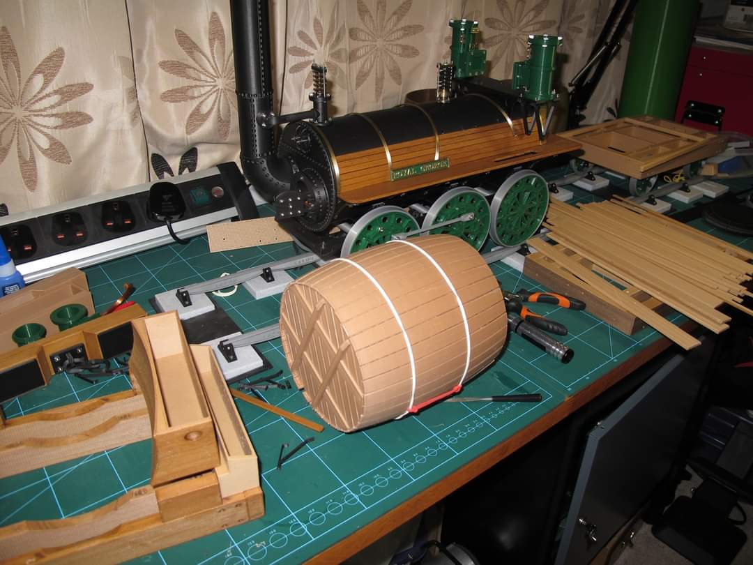
Swift loco coming along well, fitting eccentrics now, still have the Plug reg valve to fit and firebox, smokebox details to add! while I work on this here is some work I did on the Royal George in 2020 and the 3D print I did about a year later
6
39
762
Alex - That Steam Guy retweeted

28 Dec 2023
Kier Starmer will inherit THE most powerful peacetime UK state in terms of domestic law.
Far more theoretically powerful than the height of Blair's "War on Terror" Britian, and FAR more powerful domestically than the British state of 1997 Blair inherited.

2
5
33
890
Alex - That Steam Guy retweeted
Day 2 at Sorbie Tower - an introduction to wall pointing a castle!

2
14
108
1,131
The PM is not a "democratically elected" position.
This is basic stuff.

May I gently point out - the person you casually refer to as "Starmer" - is actually the democratically elected Prime Minister.
Would it not be courteous to refer to him in those terms ?
At least respect the office of PM if not the individual in post.
3
37
1,430
Digital ID has happened.
We're now in the roll-out phase.
All that dissident energy, all those podcasts, all those substacks, all those protests, all that time and money, all for nothing.
With nothing to show for any of it.
Why? Because, they are in Power and you are not.
Jun 15

🚨 SUMMARY: The UK's social media ban for children from early 2027:
- "User-to-user" apps where people create, share and interact with content (e.g. TikTok, Instagram, Snapchat, YouTube, X, Facebook) will be banned for under-16s
- WhatsApp, Signal and YouTube Kids will be exempt
- Under-16s will also be banned from livestreaming, messaging strangers on gaming apps like Discord and using disappearing messages
- 16 and 17 year olds will face nightly social media curfews and limits on infinite scrolling with more details next month
- AI "romantic companion" chatbots will be banned for under-18s
- Adults can still access social media through age checks like facial recognition, digital IDs, passports and credit cards
8
29
235
4,164
You should not want a meritocratic society. That means you, a native, has to compete with the millions of foreigners they imported against your will.
Jun 14

Only @reformparty_uk will tell the truth.
Let’s get back to truly meritocratic society.
Good to join @SkyNews this morning.
7
10
247
4,169
"Remigration is a far-Right concept referring to ethnic cleansing via the mass deportation of non-white minority populations."
You don't hate them enough!
Jun 13

Restore activists at 'white supremacy summit' with neo-Nazis: Evidence emerges on eve of vital by-election that vote for Rupert Lowe's divisive party is a grave mistake trib.al/FjLrHVl
3
2
36
932
Alex - That Steam Guy retweeted

Jun 13
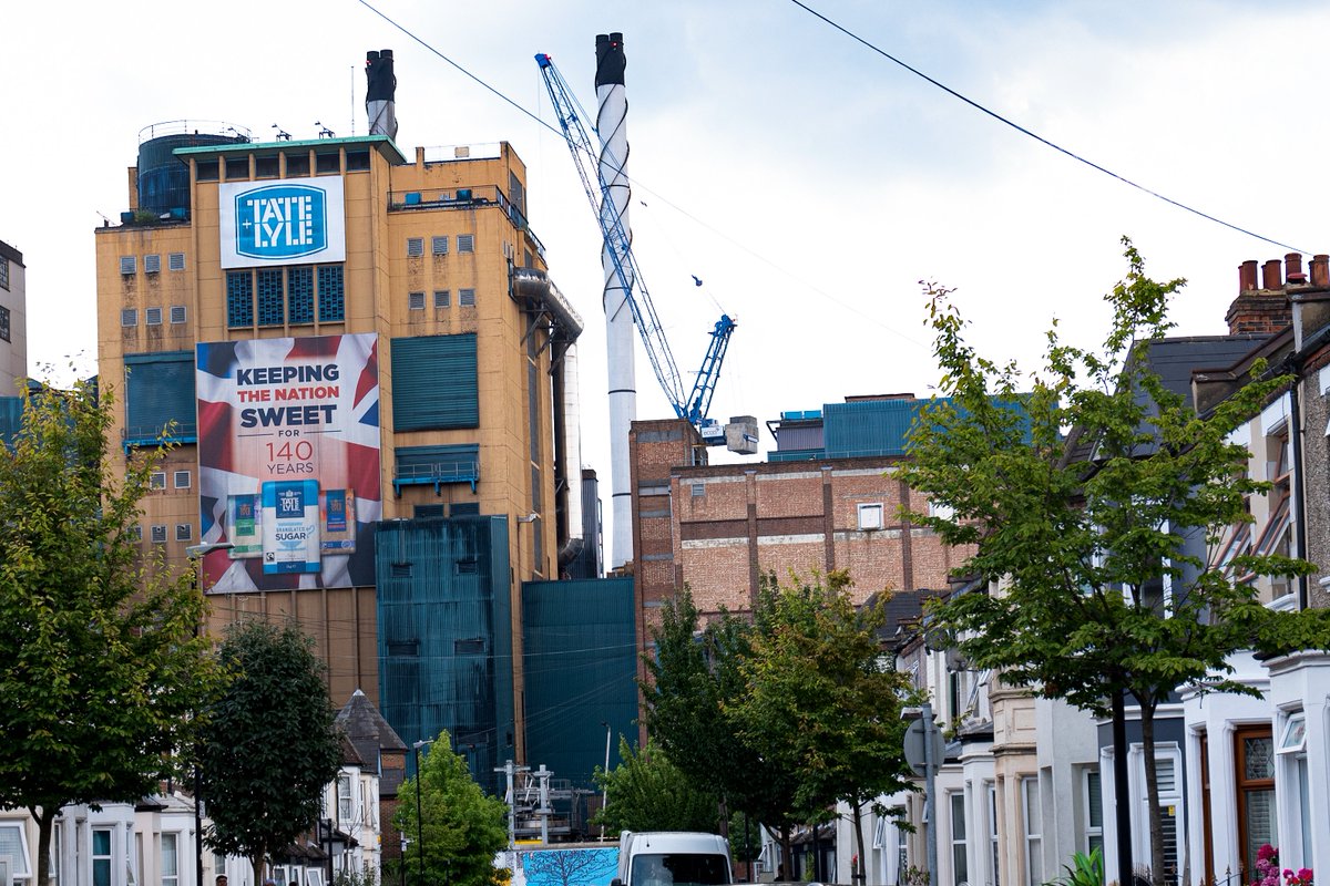
Tate & Lyle has been listed in London since 1935.
This week, it agreed to be taken over by America’s Ingredion for about £2.7bn.
The famous sugar business had already gone to the Americans in 2010.
Another great British name, gradually detached from Britain.
30
157
749
20,782
Alex - That Steam Guy retweeted
Jun 13
VOOOOOOOOTE! I'M GONNA VOOOTE!
THE PEDOPHILES IN WESTMINSTER RESPECT MY VOOOOOTE!
AHHHHH YOU'RE BLACKPILLED FOR NOT VOOOOOTING
Restore & Reform both are led by former Tories competing on how best to haggle with the boxcar door.


Anyone in Makerfield planning to vote for @RestoreBritain will land us with Burnham as Prime Minister and Ed Miliband as Chancellor.
The strapline from Lowe's acolytes that nothing will change is so moronic it's sickening. The level of abhorrence towards Restore will end them.
3
3
33
1,420
Alex - That Steam Guy retweeted

Jun 12
Compagnie des chemins de fer de l'État 231-501 class 4-cylinder de Glehn compound 4-6-2 Pacific No. 231-613 departing Gare de Saint-Lazare, Paris, with a passenger train in September 1927. The mécanicien watches Otto while smoking a Gauloise. (Denver Public Library OP-20551). 📷Otto Perry

10
56
1,098