
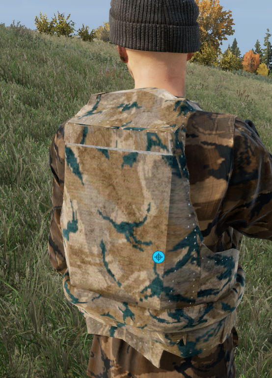
Crop jersey needs to look like this, if you wear it with no backplate it’s way too high in the back
1
278

Like on your car or on their laptop? Cars it's special stickers and for laptops it's a clear backplate
1,637


Jun 15
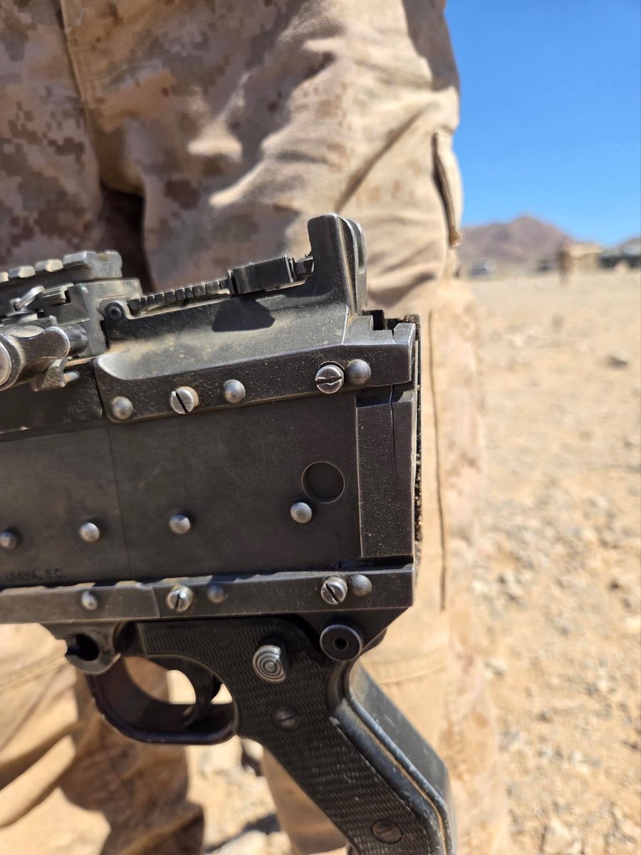
Even the steel receiver Bravo can fail under enough abuse and neglect. The hydraulic buffer assembly, with its poor design, unscrewed back into the stock, as the plunger was flush with the backplate.
instagram.com/lynndons
2
1
20
969

Jun 14
turns out the backplate of my keyboard has been rusting to the point that the paint on it is starting to flake which I guess explains why it's been failing more and more, god damn it
1
2
58

Jun 14
A threaded screw for the bolt catch reduces chances of scratching up the receiver when tapping in the bolt catch roll pin. Using a set screw for the takedown pin hole reduces the chances of launching a detent into space when installing or removing the backplate.
2
2
15
FredWash retweeted

Jun 14
@TannerSeaton71 I see that #Hottytoddy❤️💙🦈🦈🦈 On that Backplate ‼️ Let’s gooo ❤️💙🦈🦈🦈🦈
Jun 10

FULL SEASON HIGHLIGHTS AND MEASUREMENTS ❗️
Tanner Seaton
6”5 1/2
305
Class of 2028
Rivals 3 🌟
247 4 🌟
9 D1 Offers
601-667-7297
hudl.com/profile/22613471
@MCJags_Football @CoachT_Rob @jarereimonenq @MissLou365 @MSGRIDIRON @MacCorleone74 @PrepRedzoneMS @LeeAnnHerringOM
@BSonnone @247recruiting @Rivals
@ChadSimmons_ @ESPN3ALLDAY
@DemetricDWarren @TheUCReport

1
5
253

Jun 14
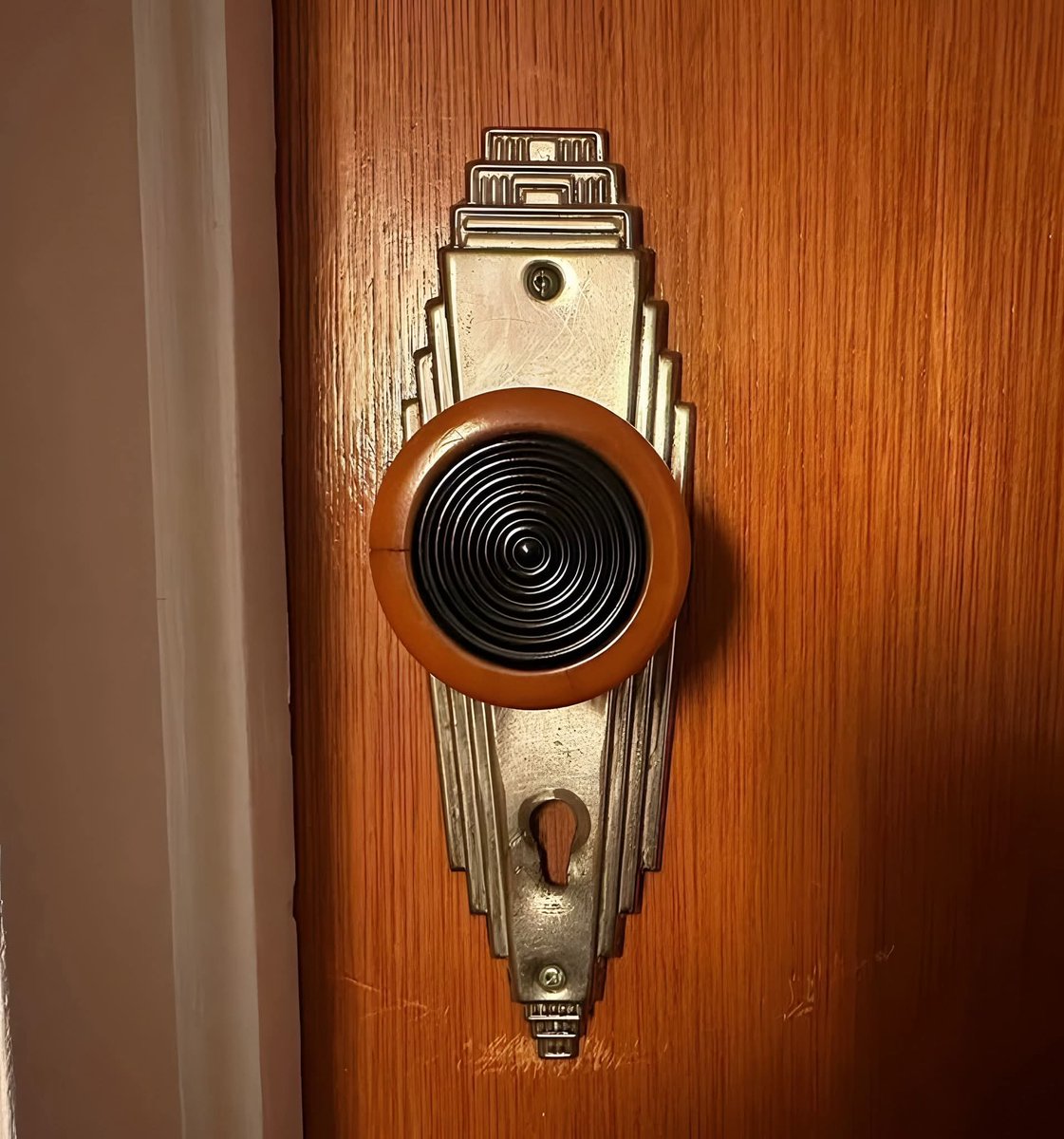
Replaced the early 1960s doorknobs in my bathroom with this 1930s Bakelite doorknob and nickel backplate.
1
2
87


Jun 13
We need the X phone with Direct-to-satellite gigabit internet anywhere on Earth without cellular towers. With structural solar glass backplate that recharges the battery via ambient light exposure.
43

Jun 13
It’s not I played the beta you can only wear the hoodies without cropping cropped like the backplate is out still I wanna be able to wear it without seeing the back plate like I want jersey all the way down
1
6
531

Jun 13
Have you ever heard of a comma, or a period?
Getting lost in the minutia of the backplate length being off by .3" is the reason the developers fucking hate you.
You're retarded. You spend your time thinking about pant length instead of playing the sport.
67


All good. My background is in marketing and tinkering.
I used GPT 5.5 to help me build the prompts.
Here is the first:
Create a detailed parametric CAD assembly of a realistic 1/10 scale nitro RC off-road
buggy. The goal is a mechanically plausible, animation-ready rolling chassis with
body shell, suspension, steering, drivetrain, nitro engine, fuel system, exhaust,
servos, linkages, covers, and exploded/inspection views.
Use millimeters.
Approximate scale:
- Wheelbase: 280 mm.
- Track width: 250 mm.
- Tire outer diameter: 90 mm.
- Chassis length: 360 mm.
- Chassis width: 120 mm.
- Engine type: small single-cylinder nitro glow engine, approximately 3.5 cc / .21
size.
General requirements:
- Build the model as separate named components and subassemblies.
- Do not merge the whole vehicle into one body.
- Make the result look like a real manufacturable RC nitro buggy, not a decorative
toy.
- Prioritize believable suspension geometry, drivetrain continuity, clearances, and
moving joints.
- Add realistic fasteners, pins, bearings, spacers, brackets, covers, and serviceable
panels.
- Keep all moving parts physically connected and mechanically readable.
- Avoid impossible intersections between suspension, wheels, driveshafts, shocks,
engine, fuel tank, exhaust, covers, and body shell.
Main subassemblies to create:
1. Chassis
- Flat aluminum chassis plate with countersunk mounting holes.
- Front and rear bulkheads.
- Raised side guards.
- Radio tray.
- Receiver box with removable lid.
- Battery/receiver battery box with removable lid.
- Steering servo mount.
- Throttle/brake servo mount.
- Fuel tank mount with rubber pads.
- Engine mount rails or blocks.
- Center differential or clutch/spur area.
- Front and rear shock towers.
- Front bumper.
- Rear bumper or rear wing mount.
- Rear wing and wing support posts.
- Body posts with height adjustment holes and body clip holes.
- Chassis braces or top deck where plausible.
- Skid plates under front and rear bulkheads.
2. Nitro engine
- Small single-cylinder nitro glow engine mounted near the center/rear of the
chassis.
- Crankcase with mounting lugs.
- Cylinder head with cooling fins.
- Glow plug at the top.
- Carburetor body with intake throat and throttle arm.
- Air filter foam element.
- Flywheel and clutch bell on the crankshaft.
- Spur gear or center gear next to clutch bell.
- Pull-start/backplate detail if space permits.
- Engine mount blocks bolted to the chassis.
- Keep access to glow plug, carburetor, fuel lines, and pull-start/backplate.
3. Fuel system
- Translucent amber nitro fuel tank with cap.
- Fuel outlet nipple and pressure nipple.
- Visible pickup line inside the tank if possible.
- Flexible fuel line from tank to carburetor.
- Pressure line from tuned pipe to tank.
- Route lines with gentle bends and no intersections.
- Keep fuel lines away from hot exhaust where practical.
4. Exhaust system
- Exhaust header from engine outlet.
- Silicone coupler.
- Polished tuned pipe mounted along one side or rear.
- Pipe hanger bracket with rubber isolator.
- Pressure nipple on pipe.
- Stinger outlet.
- Keep the exhaust clear of tires, suspension, fuel lines, and radio box.
5. Drivetrain
- 4WD buggy drivetrain.
- Front and rear differential housings.
- Center differential, slipper, or clutch/spur gear assembly.
- Clutch bell and spur gear near the engine.
- Center driveshafts to front and rear gearboxes.
- Dogbone or CVD shafts from differentials to all four wheel hubs.
- Output cups at differentials.
- Axle stubs through each wheel hub.
- Hex wheel hubs and axle nuts.
- Bearing seats at hubs and differential outputs.
- The drivetrain should visibly connect the nitro engine/clutch/spur area to all four
wheels.
- Use simplified gear teeth if needed, but make the gear train mechanically readable.
6. Front suspension and steering
- Independent double-wishbone suspension on both front wheels.
- Upper and lower A-arms with hinge pin holes.
- C-hubs or caster blocks.
- Steering knuckles/uprights with bearing seats.
- Adjustable turnbuckles/tie rods.
- Steering rack or bellcrank system.
- Steering column/linkage from steering servo horn to bellcrank/rack.
- Front shock tower.
- Pose front wheels turned slightly left, about 10-15 degrees.
- Leave clearance for full steering lock and suspension compression.
7. Rear suspension
- Independent double-wishbone suspension on both rear wheels.
- Rear lower A-arms.
- Rear upper links or upper A-arms.
- Rear hubs/uprights with bearing seats.
- Rear hinge pin mounts.
- Rear shock tower.
- Slight rear toe-in is acceptable.
- Leave clearance for driveshaft movement and suspension travel.
8. Realistic coilover shocks
Create four realistic mounted coilover shocks. Do not make springs as floating
stacked rings.
For each shock:
- Create a named subassembly:
Shock Body, Shock Shaft, True Helical Coil Spring, Upper Spring Retainer, Lower
Spring Retainer, Upper Eyelet, Lower Eyelet, Mounting Screw/Pin, Spacers/Washers.
- The spring must be a continuous helical coil or sweep, not separate torus rings.
- The spring must wrap around the shock body/shaft and be captured between retainers.
- The shock body and shaft must be aligned on the same centerline.
- Upper shock eyelet attaches to the shock tower.
- Lower shock eyelet attaches to the moving lower suspension arm, not to the chassis
plate.
- Add spacers/washers so shocks clear towers and arms.
- Shocks must not pass through chassis plates, side guards, towers, wheels,
driveshafts, or arms.
- Front shocks should lean inward/backward in a plausible RC buggy layout.
- Rear shocks should lean inward/forward or slightly inward.
- Ride height should place shocks about 35-45% compressed.
9. Servos, brake, and throttle linkage
- Add steering servo with servo horn connected to steering rack/bellcrank.
- Add throttle/brake servo with dual-arm horn.
- Add throttle linkage rod from servo to carburetor throttle arm.
- Add brake linkage rod from servo to center brake lever.
- Add return spring on throttle linkage.
- Add center brake disc and caliper near center drivetrain.
- Add brake cam or lever connected to caliper.
- Use small rods, bellcranks, springs, clevises, and servo horns.
- Make linkages physically readable and clear of moving parts.
10. Covers, guards, and service panels
- Add removable front gearbox cover.
- Add removable rear gearbox cover.
- Add center spur/clutch gear cover.
- Add receiver box lid.
- Add battery box lid.
- Add side guards/splash guards.
- Add optional transparent inspection-cover versions for gearbox and center gear
covers.
- Covers should have screw holes, bosses, wall thickness, and serviceable fasteners.
- Covers must not intersect gears, shafts, steering, suspension, or drivetrain
movement.
11. Wheels and tires
- Four separate wheel/tire assemblies.
- Separate tire, rim, hex hub, axle nut, and bearing detail.
- Black rubber tires with simple tread grooves.
- Gray or white plastic wheels.
- Wheel hubs should align with axle stubs and driveshafts.
12. Removable body shell
Add a realistic removable 1/10 scale nitro buggy body shell.
Body shell requirements:
- Separate named component: Removable Lexan Body Shell.
- Thin vacuum-formed polycarbonate/Lexan shell, approximately 0.8-1.2 mm wall
thickness.
- Low pointed nose over front shock tower.
- Raised cockpit/cab area near center.
- Side pods over fuel tank/radio tray area.
- Rear taper around engine and pipe.
- Rear deck opening around engine/cooling head.
- Cutouts/openings for:
engine cooling head
glow plug access
fuel tank cap access
pull-start/backplate access if visible
tuned pipe clearance
air filter clearance
shock tower clearance
body posts
- Four body post holes aligned to posts.
- Reinforced washer pads around post holes.
- Body clip placeholders at each post.
- Body must not intersect wheels, shocks, suspension, engine, fuel tank, exhaust,
steering, or drivetrain through normal motion.
- Make the body semi-transparent smoky blue or clear Lexan so internal parts remain
visible.
- Add molded edges, wheel arch cut lines, hood ridges, side pod ridges, cockpit
contours, rear deck vents, and optional thin decal-like accent panels.
- Body should be removable with clips, not permanently bolted.
13. Required animation and joints
Grounding:
- Ground the main chassis plate.
- Rigidly attach fixed brackets, bulkheads, towers, receiver box mounts, fuel tank
mounts, and engine mounts to chassis.
Suspension joints:
- Revolute joints at all front and rear lower A-arm hinge pins.
- Revolute joints at all upper A-arm or upper link pivots.
- Revolute or ball-style joints at steering knuckles/uprights.
- Revolute or ball-style joints at camber links and tie rods.
- Travel limits:
front wheel vertical travel about 20-25 mm
rear wheel vertical travel about 25-30 mm
- Add bump stops and droop stops.
- Named poses:
Ride Height
Full Bump
Full Droop
Shock joints:
- Revolute joints at upper and lower shock eyelets.
- Slider or cylindrical joint between shock body and shock shaft.
- Compression limits:
front shock travel about 18-22 mm
rear shock travel about 22-28 mm
- Link shock compression to lower arm movement if supported.
- Name joints:
FL Shock Upper Revolute
FL Shock Lower Revolute
FL Shock Slider
FR Shock Upper Revolute
FR Shock Lower Revolute
FR Shock Slider
RL Shock Upper Revolute
RL Shock Lower Revolute
RL Shock Slider
RR Shock Upper Revolute
RR Shock Lower Revolute
RR Shock Slider
Steering joints:
- Revolute joint at steering servo horn.
- Revolute or ball joints at steering bellcrank/rack pivots.
- Ball/revolute joints at tie rod ends.
- Motion link from steering servo horn to steering rack/bellcrank and front wheels.
- Steering limits: approximately -25 degrees to 25 degrees.
- Named poses:
Steering Full Left
Steering Center
Steering Full Right
Drivetrain joints:
- Revolute joints for all four wheel axles.
- Revolute joints for front and rear differential input/output shafts.
- Revolute joints for center driveshafts.
- Revolute joints for clutch bell, spur gear, and center differential.
- Motion links so rotating clutch bell/spur gear rotates center shafts, differential
inputs, driveshafts, and all four wheels.
- Exact differential behavior may be simplified, but the drivetrain should visibly
rotate as a connected system.
- Named motion study:
Drivetrain Rotation
Nitro engine motion:
- Revolute joint for flywheel/clutch bell assembly.
- Optional simple crankshaft revolute.
- Optional piston slider linked to crankshaft rotation if feasible, but do not let
this block the main vehicle completion.
Throttle/brake motion:
- Revolute joint at throttle/brake servo horn.
- Revolute joint at carburetor throttle arm.
- Revolute joint at brake lever/cam.
- Motion link from servo horn to carburetor arm.
- Motion link from servo horn to brake lever.
- Named poses:
Idle
Full Throttle
Brake Applied
14. Motion studies / animation modes
Create or prepare named motion tests if supported:
- Suspension Compression Test: all four wheels move through bump travel, arms rotate,
shocks compress, no major intersections.
- Steering Sweep Test: front wheels sweep full left to full right, servo horn and tie
rods move.
- Drivetrain Rotation Test: clutch bell/spur rotates and driveshafts/wheels rotate.
- Throttle and Brake Linkage Test: servo moves carburetor arm and brake lever.
- Ride Height Pose: chassis level, suspension slightly compressed, front wheels
turned slightly left.
15. Exploded and inspection views
Create an exploded view or exploded duplicate arrangement beside or above the
assembled buggy. Do not destroy the main assembled model.
Exploded view should separate:
- Body shell vertically 120-160 mm above chassis.
- Body clips slightly above body posts.
- Wing and wing mount upward/rearward.
- Fuel tank upward/right.
- Receiver box and battery box lids upward.
- Tuned pipe and exhaust header outward to side.
- Center gear cover upward.
- Front gearbox cover forward/up.
- Rear gearbox cover rearward/up.
- One front suspension corner outward.
- One rear suspension corner outward.
- One shock absorber exploded into spring, body, shaft, cap, retainers, and eyelets.
- One wheel/tire assembly outward showing axle nut, hex hub, rim, and tire.
- Brake and throttle linkages slightly lifted but still aligned.
Add inspection/visibility states if supported:
- Assembled Mode
- Body Installed
- Body Hidden
- Body Transparent
- Covers Hidden
- Transparent Covers
- Exploded View
- Motion Test Mode
16. Materials and colors
Use realistic RC nitro buggy materials:
- Black molded plastic: suspension arms, bulkheads, covers, side guards, receiver
box, bumpers, air filter foam.
- Brushed aluminum: chassis plate, engine mounts, chassis braces.
- Silver steel: hinge pins, shafts, screws, springs, bearings, shock shafts.
- Blue or purple anodized aluminum: cooling head, shock caps, spring retainers, wheel
hexes, turnbuckles.
- Translucent amber plastic: fuel tank.
- Black rubber: tires, fuel tubing, pipe coupler.
- Gray/white plastic: wheels.
- Polished metal: tuned pipe and exhaust header.
- Brass/gold: glow plug, carburetor details, fuel nipples.
- Semi-transparent smoky blue or clear Lexan: removable body shell.
17. Final quality checks
Before finishing, verify:
- Shocks are physically attached at both ends.
- Springs are true helical coils, not floating ring stacks.
- Shocks do not pass through chassis or towers.
- Lower shock mounts are on moving suspension arms.
- Steering linkage connects servo to wheels.
- Drivetrain visibly connects engine/clutch/spur area to all four wheels.
- Driveshafts clear suspension through travel.
- Fuel lines and pressure lines are routed cleanly.
- Exhaust does not intersect suspension, wheels, fuel tank, or body.
- Body shell has cutouts for nitro engine, fuel cap, air filter, tuned pipe, and body
posts.
- Covers are removable or suppressible.
- Internal parts can be seen using transparent/hidden body and cover modes.
- Exploded view preserves a complete assembled model.
- All major parts and joints are named clearly.
1
8
464
