
Jun 17
They usually have a smaller RPM range they spend most of their time in. EVs demand high stall torque and high efficiency at high rpm low load. There's voltage considerations as well, they use field weakening reluctance torque to get higher RPM than the voltage would allow.
The IPM inrunner style motor basically lets them cheat a little bit and get almost 2 different motor types just by adjusting stator currents. Most other uses don't have such wide RPM and load demands so you don't see them focusing on IPM designs like EVs do.
1
29

Mar 17
I think this paper is a nice read but I thought it is worth clearing up some misconceptions about reflected inertia and gear ratio.
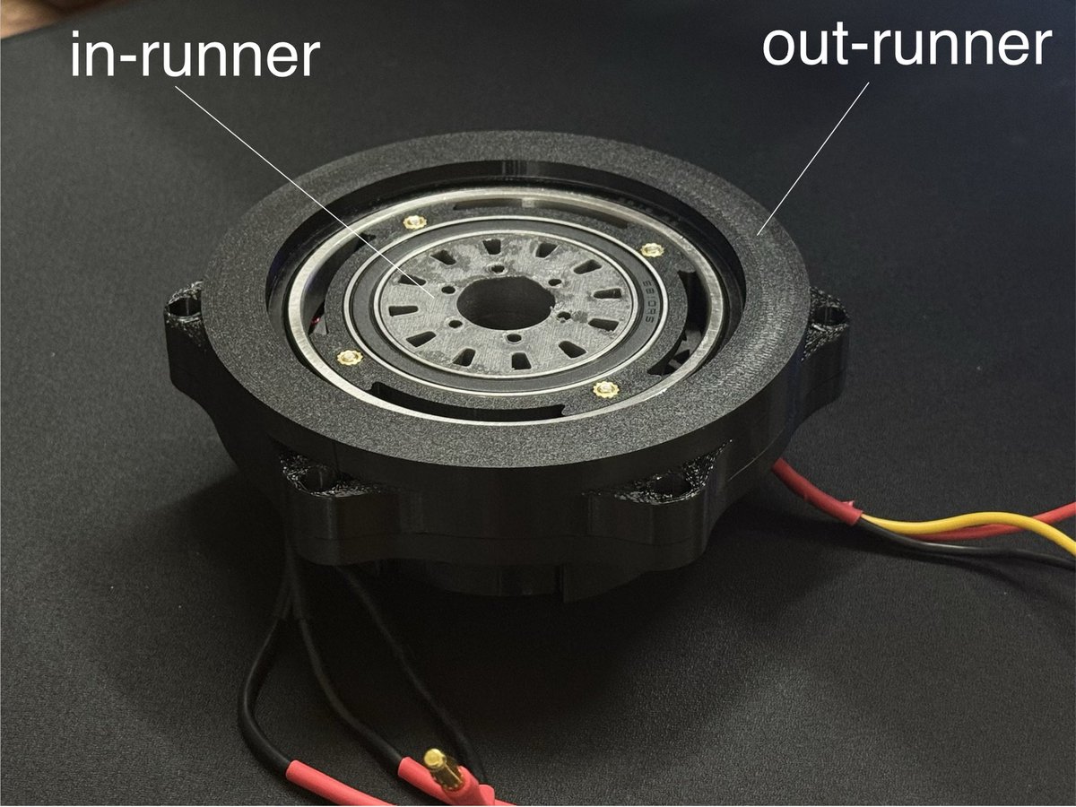
First of all, if you keep output torque constant, reflected inertia is actually independent of gear ratio (if you ignore gear friction and mass). You can try different combinations of gear ratio and rotor inertia, but if you have output torque as a constant, regardless of the combination you picked, you'll end up with the same reflected inertia. This is a pretty important intuition to build, and it's also the reason why the reflected inertia between outrunner actuators and inrunner actuators is pretty much the same for the same torque (but inrunners have slightly lower because of differences in mechancial implementation). And also why linear actuators roughly have the same reflected inertia as a rotary actuator with the same joint torque. It's a little harder to compare reflected inertia of linears vs rotaries because reflected inertia in a 4-bar linkage is non linear, and also depends if you invert the gear train or not :)
The part I'm not sure about is that the gear ratio is decreased by an order of magnitude (from 288:1 to 15:1) and to compensate for the loss in torque, they use an axial flux motor. Axial flux motors are cool but they don't give you THAT much more torque.
Also, torque transparency can be decent up to gear ratios of 100 or even higher. Gearbox efficiency motor side losses dictate an actuator's ability to sense output torque, and gear ratio is a just multiplier of that effect.
Ie high gearbox efficiency means you can get away with higher gear ratios without sacrificing proprioception. Involute gear teeth are very efficient, and given an efficient gear tooth design, gearbox efficiency is determined by how many stages you have, not necessarily gear ratio. Single-stage = very good, two-stage = pretty good, three-stage = decent. And the converse is true as well: low efficiency gearing, like harmonic drives, means that you will always need an external torque sensor, regardless of gear ratio. (Not only do harmonic drives have low efficiency, but also their efficiency is non linear with speed and torque)
It's easy to point fingers at gear ratio as the parameter to blame for sim2real gaps. However a well designed actuator with a 30:1 gear ratio and a smaller/lighter motor often times outperforms a 15:1 actuator with a larger motor if you also care about total mass, thermal performance, and battery life. But I do think for a hand that only needs to do light dexterous work like origami, going down the low-ratio route is a sure-fire way to make your models happy
Feb 26

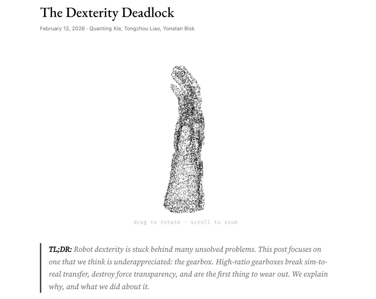
Why does manipulation lag so far behind locomotion? New post on one piece we don't talk about enough: The gearbox. The Gap You've probably seen those dancing humanoid robots from Chinese New Year. Locomotion isn't entirely solved; but clearly it's on a trajectory. But we haven't seen anything close for manipulation. 𝗪𝗵𝘆? When sim-to-real transfer fails, the instinct is to blame the algorithm. Train bigger networks. Crank up domain randomization. Those approaches have made real progress; we don't deny that. But we started wondering: are we treating the symptom or the disease? The Hardware Bottleneck: Fingers are too small for powerful motors. So most hands use massive gearboxes (200:1, 288:1) to get enough torque. But those gearboxes break everything manipulation needs:
• Stiction and backlash are complex to simulate. Policies trained on smooth physics hallucinate when they hit that reality.
• Reflected inertia scales as N². At large gear ratio, the finger hits with sledgehammer momentum.
• Friction blocks force information. The hand becomes blind.
And they're the first thing to break. What we are trying to build at Origami, we cut the gear ratio from 288:1 to 15:1 using axial flux motors and thermal optimization. The transmission becomes more transparent: backdrivable, low friction, forces propagate to motor current. Early signs are encouraging. Still running quantitative benchmarks. Why Interactive? I love how Science Center uses interactive devices to explain complex ideas. I want to borrow this concept and help people understand the hard problems in robotics better visually. The post has demos where you can toggle friction, slide gear ratios, watch the sim-to-real gap widen in real-time. What's inside:
• Interactive demos (friction curves, N² scaling, contact patterns)
• Comparison table: 14 robot hands by sim-to-real gap and force transparency
• The math behind why low-ratio matters
Read it here: origami-robotics.com/blog/de… We're not claiming we've solved dexterity. The deadlock has many pieces. But we think this one's foundational. Curious what you think.
1
2
26
3,938


Hmm I’m curious what would happen if I add planetary gear on my design and use outrunner to spin ring gear instead of being stationery and input sun gear be the inrunner
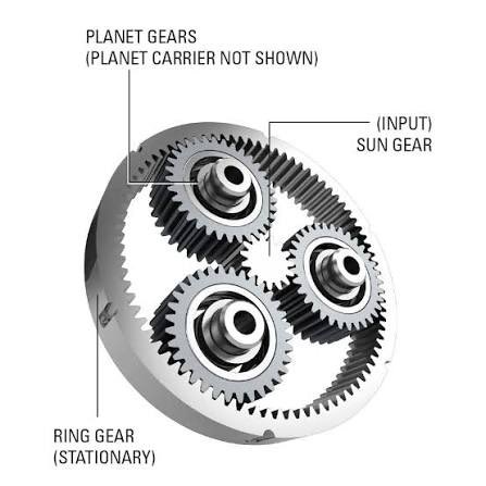

I’ll redesign the outer ring later on, this design is easy to assemble and disassemble easily for testing and fixing stuff.
3
1
30
3,335


12 Sep 2025
Power and torque densities are always trending up but very slowly, marginal improvements.
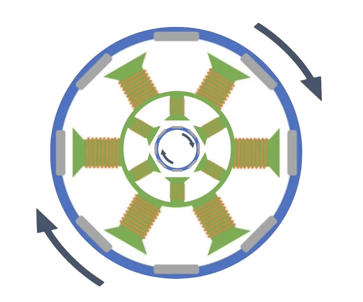
For robots the bigger problem is overheating motors, so I’m seeing more clever ways to flux heat out of the motors. Lots inrunner motrs (spinny part in the middle, hot part on the outside)
1
5
269
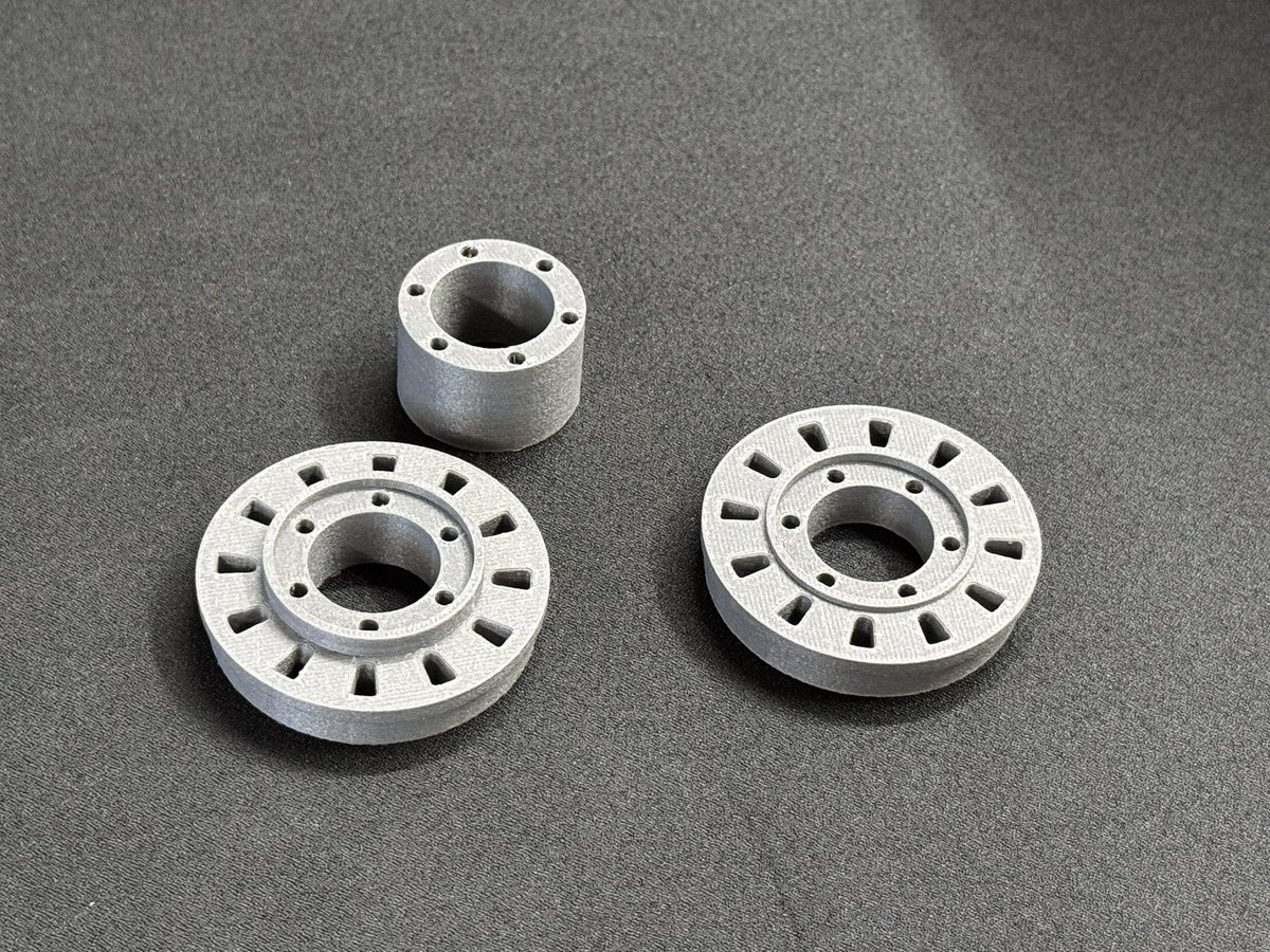
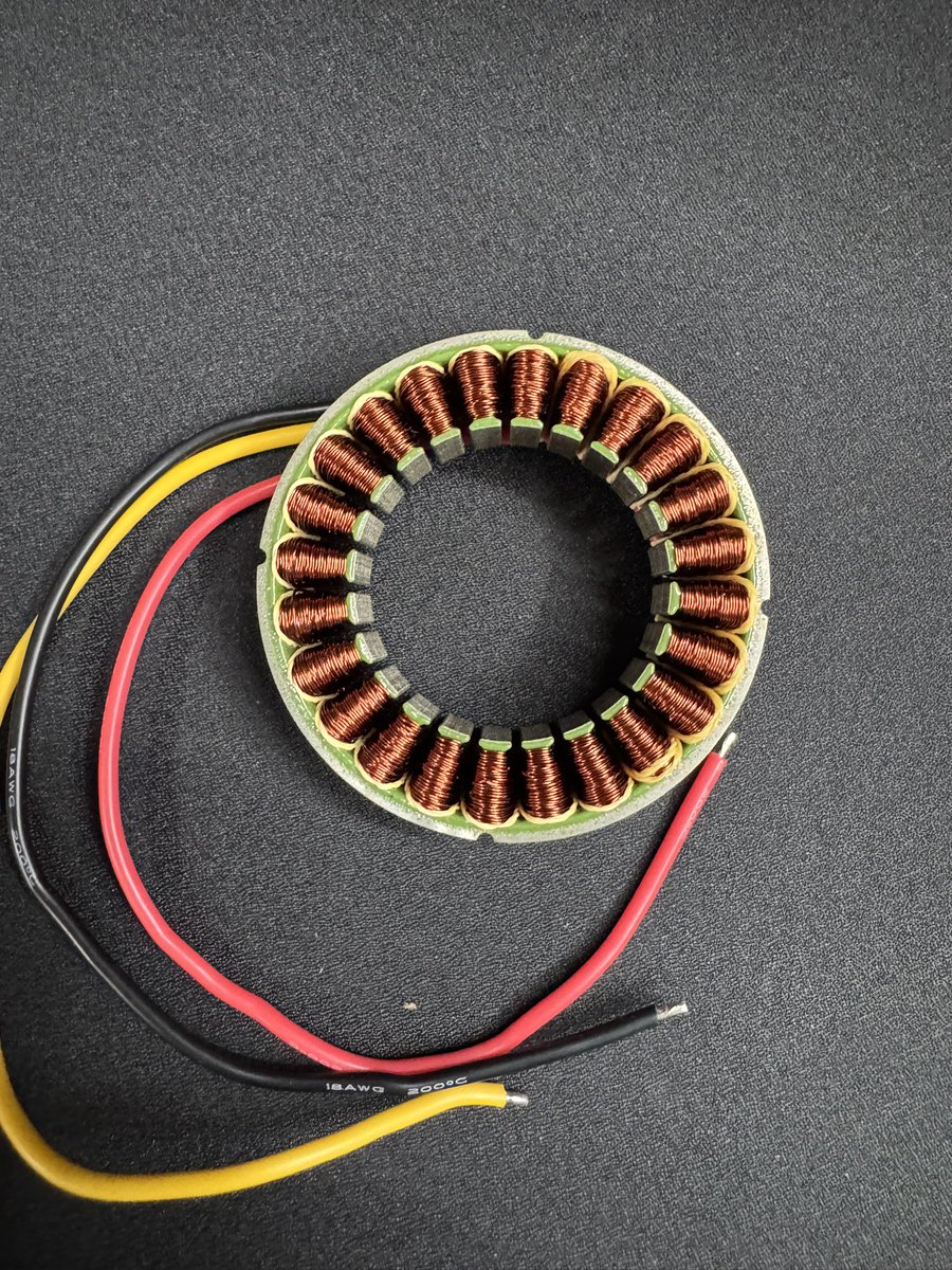
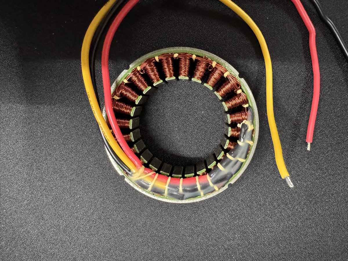
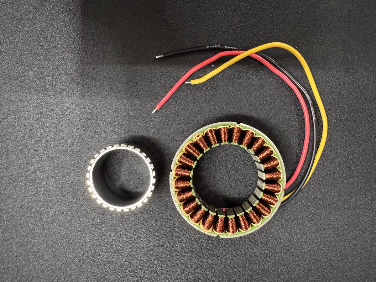
Update on the Twine Spinner project
Finally found a proper inrunner stator core — moving away from my custom 3D-printed/SMC stator experiments for now. This core should give way better magnetic performance, durability, and heat handling, so I can focus on optimizing the double rotor / double stator design instead of fighting with material limits.

2
5
60
2,181


It’s been nearly a couple of years since we last touched it, but Air Maxx it’s finally getting some much needed TLC!
It’s getting brand new motors with a gearbox shaft that will be less of a pain to remove hubs and we have replaced the weapon outrunner motor with an inrunner.
3
83

29 Jun 2025
These look like the poles are segmented and then assembled by welding, which is interesting because this level of winding fill would be very hard to achieve automatically otherwise.
Two models are probably for different markets/tiers. The smaller is probably for 250W countries and the larger for 750W. For torque-dominated applications operating for extended periods of time, there are probably thermal considerations that this inrunner design solves.
This essentially has to be a mid drive, though.
The main question I have about most of these ebike companies coming on the market is really who the target audience is. Most people buying an expensive ebike are probably buying a better *bike* that happens to have a motor, dominated by incumbent brands who have seen little competition from China for now (you can probably build a full carbon MTB for less than half price that will mechanically perform in the same ballpark in China, but there is insane brand loyalty here).
The low end ebike market seems to be dominated by the minimum viable Bafang integrators overseas, and NYC's UL cert requirement has not meaningfully created a skill floor (I think the requirements are not particularly strict anyway). Unagi tried to make premium eScooters, and I rarely see them now (they did get a fleet contract with Google). Boosted died making a scooter.
Ninebot came out with a better-integrated bike, but it looks heavy and mostly for the bikeshare market (which IMO is boring and commodity because the bike share bikes are neither good bikes nor good ebikes so it doesnt really matter how they are designed).
On the other hand, if they go beyond eBikes as they say, there's a huge market there. I'm not sure if the performance requirements and the fact that Rivian can full stack the electronics is particularly meaningful at the scale they are talking about (surprisingly few engineers are required to do anything if you can control the number of PMs and meetings involved). But certainly there is a cultural avoidance of the electrification stack outside of large companies in the West so this could be an interesting thing to watch.
I just wish someone would push for a new regulatory category of light electric vehicles (bring back NEVs or neighbourhood electric vehicles!). Make three wheeled carts great again!
1
22
773

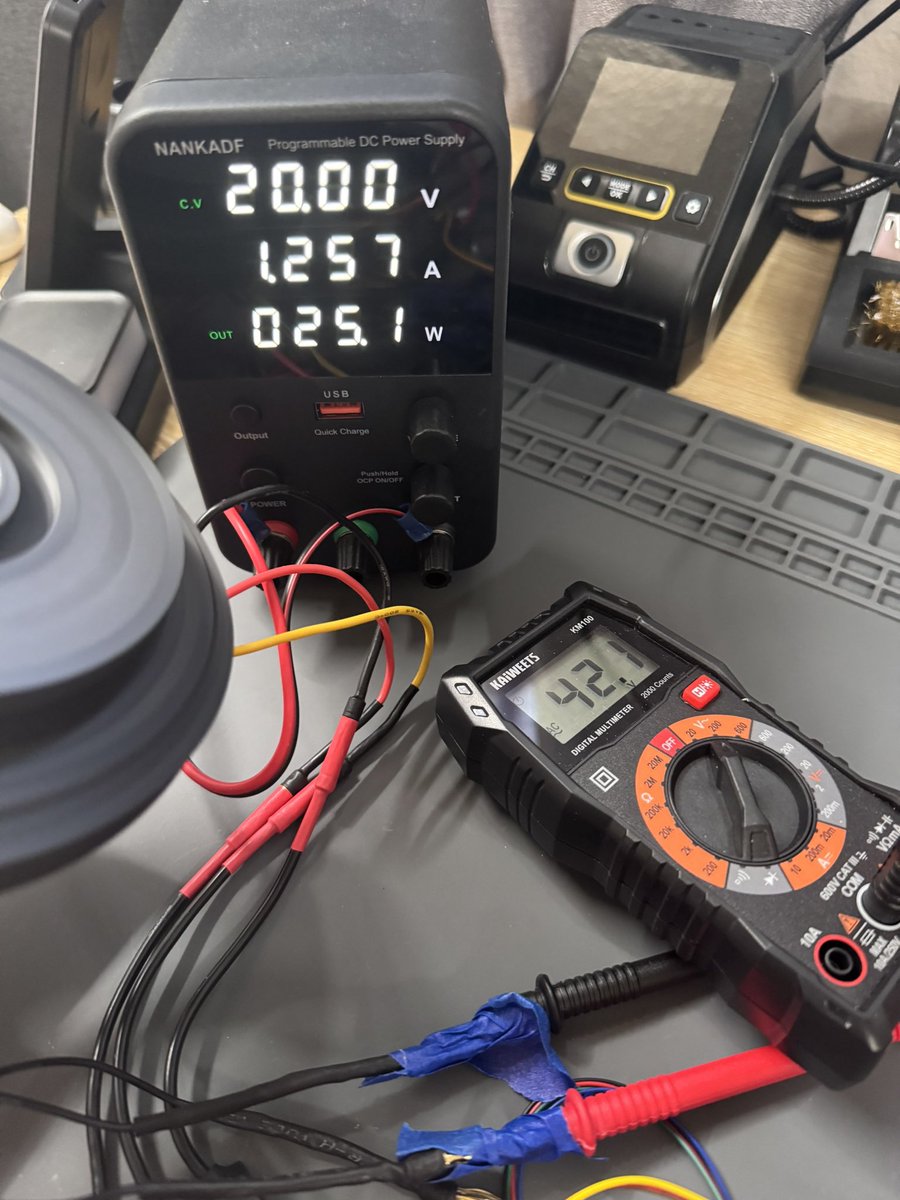
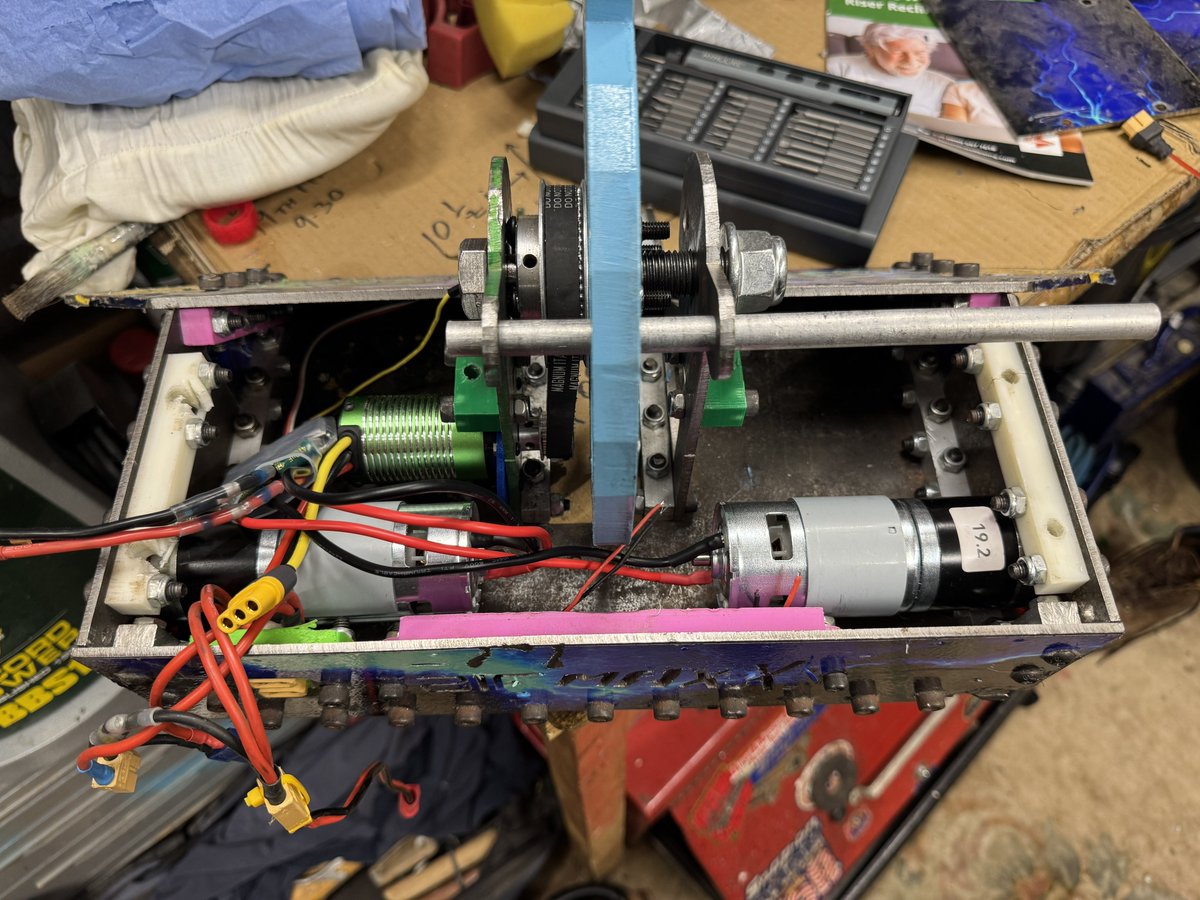
Okay very interesting results. Torque is better than expected but maybe not good enough.
1. Single phase winding resistance of 1.5ohms
2. 12S14P
3. Running about 16V with unlimited current basically ( I =V/R) so this wobble is from 10 amps…
4. Stator and rotor is currently standard PLA. Will try iron filled PLA next to see how this changes @ing_bue
5. Kicking myself for not doing an outrunner, but thought and Inrunner would be cool to directly integrate into and actuator
6. Would not wish manual stator winding on my worst enemy
Okay now on to main projects!! Gotta focus!

1
5
477


7 Mar 2025
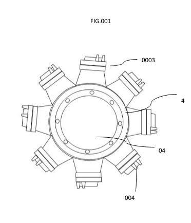
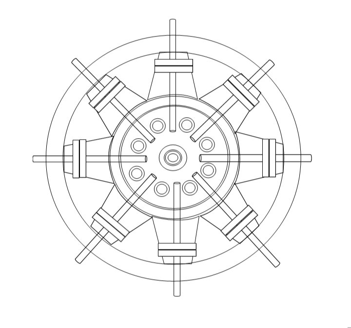
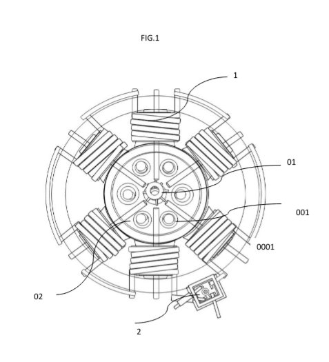
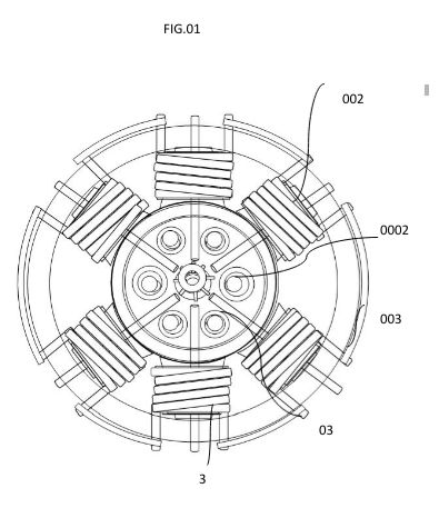
ELECTROMAGNETIC TRANSDUCER PNEUMATIC AIR PUMP COMMUTATOR CAGE BALL BARING BRACKET INRUNNER ROTARY MOTOR SUBJECT NOT LIMITING TO ADDITIONAL SYSTEM OR STRUCTURE POTENTIOMETRIC RANGE DESIGN INVENTOR JERMAINE MORTON
33
20 Feb 2025
I recently did an inrunner super carefully and got 33% (including wire enamel) and I was looking at my hands like, fellas, come on
2
113