
Orbiting Computing Model – For @elonmusk and anyone thinking about SpaceX orbital AI data centers
Here’s an orbital compute architecture that might help frame the discussion:
Separate long-life orbital infrastructure from short-life compute.
Instead of building fully self-contained, one-shot compute satellites, imagine permanent orbital grids that provide the durable backbone: power generation, heat rejection, structural support, routing, and berthing. Then treat the actual compute sections as consumables. The backbone is designed to live for decades; the compute modules are designed to run hard for a few years, deorbit, and be replaced by newer hardware. That separation matches the real cadence mismatch between long-lived space infrastructure and short-lived AI accelerators.
Permanent backbone, disposable compute
Each grid is a robust, long-term orbital utility platform: large solar arrays, substantial radiator area, power conditioning and distribution, internal data routing, and many berthing points. This is where the heavy, expensive, durable hardware lives.
The compute modules are the opposite. They are relatively simple radiation-tolerant GPU or accelerator bricks that can be mass-produced, launched cheaply, docked to the backbone, run for perhaps 3–5 years, and then discarded and replaced. That avoids pretending fast-moving compute hardware should be treated like 20-year spacecraft bus hardware. It also means the expensive power and cooling backbone is amortized over many compute generations rather than reflown every cycle.
Shared thermal mounting surfaces
The grid’s faces are shared thermal mounting surfaces that pull heat out of the compute modules and into the backbone’s radiators.
Conceptually, each berthing zone is a structural cold plate tied into the permanent thermal network. Internally that can evolve over time. Early versions might use conduction-heavy spreaders and embedded heat pipes; later versions might use liquid-cooled cold plates or loop heat pipes to move heat from dense compute sections out to large deployable radiators. The important point is architectural, not doctrinal: the permanent grid owns the thermal plumbing and radiator mass, while the disposable module only presents a standardized mechanical and thermal interface.
The contact surface can be a “bumpy flat” topology: mostly planar, but with controlled surface features that increase effective area, improve compliance, and help alignment. Compliant thermal interface materials plus an active clamp provide the preload needed for good thermal contact even with manufacturing tolerances, orbital dynamics, and repeated docking cycles.
To address vibration and dynamic loads in orbit, the shared mounting surface can incorporate damped interfaces or tuned mass absorbers at the berthing zone level. The eccentric cam latching provides high, repeatable mechanical preload (targeting several kN per module depending on size) to maintain thermal contact pressure even under micro-vibrations from docking events or attitude maneuvers. Long-term contact reliability can be monitored via embedded sensors in the backbone reporting interface temperature deltas and preload status, triggering robotic intervention only when thresholds are exceeded. This keeps routine operations fully automatic while preserving long-term contact reliability over hundreds of docking cycles without fluid connections or complex mechanisms on the disposable module side.
So coolant, if used, stays inside the backbone. The compute module only sees a passive interface, not fluid hookups.
Docking, magnets, guide geometry, latching, and robots
Docking is designed to be forgiving rather than finicky.
Layered Approach:
1. Capture
A capture-envelope system, nets, tethers, or something functionally similar, grabs incoming modules that are roughly in the right approach corridor. It does not need millimeter-level precision, just enough to keep them from bouncing off or becoming debris.
2. Ring-toss style magnetic seating
Once the module is in the neighborhood of a berthing site, magnets in the backbone’s seating pocket pull it toward a central guide feature on the permanent side. Instead of trying to line up two perfectly flat faces in free space, the module is brought down over a short central guide feature in a motion closer to ring-toss than precision docking. The backbone presents the peg, and the module presents a matching annular opening or socket. Magnets do the last part of the pull-in and help keep the module from skidding away if the approach is slightly off.
3. Filleted elliptical guide spike
The central guide feature does not have to be a perfectly round pin. It can be a short, stout, slightly elliptical alignment spike or boss with a rounded, snub-nosed top and generous fillets where it meets the base. That geometry does several things at once. First, it is mechanically forgiving: if the module comes in a bit off-center, the rounded nose and curved sides turn the contact into a sliding, centering motion instead of a hard collision. Second, the slight ellipticity means the module no longer has unlimited rotational freedom about the centerline. As it settles over the guide feature, it is nudged into one of two approximate orientations 180 degrees apart. In other words, the docking geometry itself clocks the compute brick into one of two acceptable states without demanding exact rotational alignment during approach.
4. What the guide spike does and does not do
The central spike is mainly an alignment feature, not the primary structural or thermal path. Its job is to convert rough placement into repeatable coarse alignment. Once the module is seated, the surrounding flat mounting surface handles the real work: structural support, thermal conduction, and final clamp preload. That keeps the spike short, strong, and tolerant of side loads rather than turning it into a delicate load-bearing pin.
5. Why two orientations may be enough
Two allowed orientations may actually be preferable. If the thermal, power, and optical interfaces are designed symmetrically enough, there is no need to distinguish between a unique front and back rotational state. The compute module just needs to land in one of two acceptable clockings. That is much easier to achieve passively than requiring a single exact angle.
6. Automatic hard capture with eccentric cams
Soft capture and alignment are only the first part of docking. Final latching can be handled by giving the compute module simple projecting rims or flanges around the base of the compute section, just outside the main thermal contact area. Matching eccentric cams on the backbone or framework side then rotate over those rims and pull the module down as they turn, much like an old-fashioned home window latch. This gives the system a clean hard-capture stage after the magnetic seating stage. The magnets and guide spike get the module into the right place; the cams apply the final mechanical preload.
Because eccentric cams provide mechanical advantage, a relatively simple local actuator can generate a substantial and repeatable clamp force. That is exactly what the thermal interface wants: a known load pressing the module base into the shared mounting surface. It also gives the structure a positive retention mechanism that does not depend on magnets alone.
In the nominal case, this latching sequence can be automatic. Sensors confirm that the module has seated properly, the cams rotate into place, and the module is pulled tight against the thermal mounting surface. Only if a cam fails to complete its travel, a sensor reports inadequate preload, or the module mis-seats does a robot need to intervene. That means the robots become exception handlers rather than the normal mechanism for every docking cycle.
7. Robots for off-nominal cases and servicing
Small tethered robots still matter, but now mostly for recovery and maintenance rather than routine docking. Think Optimus-scale robots that live on the backbone side. They are stored in compact, radiation-shielded garages built into the framework, where they charge and connect to the grid’s control system. If the normal latching sequence completes successfully, the robots do nothing. If something goes wrong, a partial seat, a failed cam rotation, a jammed latch, a need to re-seat a module, or replacement of a grid-side optical receiver cartridge, then a robot walks or climbs out along the structure, grabs standard handles, and performs the corrective action. Tethers provide power and data and ensure the robots never become free-flying debris.
More broadly, the grids and berthing interfaces are designed from the start for robotic assembly and servicing rather than depending on astronauts. Current ISAM work already assumes robotic assembly is central to building and maintaining large modular orbital structures, especially backbones that would be too large or too repetitive to assemble entirely by EVA.
The bootstrap missions that bring up the first backbone structures can be uncrewed and robot-assisted, and the mature system can remain robot-operated in normal service. Astronauts are optional for unusual inspection, repair, or demonstration missions, not a standing requirement. That design choice matters because it keeps risk, cost, and operational complexity closer to satellite operations than to human space station operations.
This general approach follows the same logic used in self-aligning docking systems more broadly: do not demand perfect first contact; use shaped guide features to turn imperfect contact into proper alignment, then use a separate hard-capture mechanism to lock the interface down.
Power, cooling, and data
Once seated:
• Cooling
The module’s base is clamped against the shared thermal mounting surface. Heat flows through the compliant thermal interface into the backbone’s internal thermal network, then out to large radiators. This matters because an orbital data center is fundamentally a thermal machine. In orbit there is no ambient air to convect heat away, so waste heat has to be transported to radiator surfaces and emitted as infrared radiation. That makes thermal management, radiator area, and radiator orientation central design constraints, not afterthoughts.
• Power
Power is delivered through robust contacts or inductive couplers embedded in the berthing pocket. Inductive transfer makes the system tolerant of small gaps and misalignment and avoids delicate, high-current connectors on hardware that will be swapped frequently.
• Data and control
Data and control stay optical, with no high-density electrical backplane on the disposable side. Short-range links between each module and its grid use low-power optical emitters, initially high-speed LEDs, with the option to move to faster diode lasers later, and matching photodiode receivers embedded in baffle-lined berthing pockets. The baffles confine and absorb stray light, and the links shut down automatically when no module is present.
Because the filleted elliptical guide spike only allows the module to settle into one of two orientations 180 degrees apart, the optical interface does not need to be a full circular ring. It can be reduced to two baffled optical zones on opposite sides of the guide feature. Each zone contains emitters and receivers on both the module side and the backbone side, arranged so that in either of the two allowed docking orientations both optical zones still line up correctly. That means both optical connections can be used in either allowed orientation rather than leaving half the interface idle. The docking geometry simplifies the optics: the guide spike and mounting surface establish axial and lateral position, while the 180-degree symmetry removes the need for exact rotational alignment.
Early versions can use high-speed LEDs in those two optical zones because LEDs are simple, forgiving, and already fast enough for short enclosed links. Later versions can swap in diode lasers for higher throughput without changing the docking pocket’s sensors or its mechanical geometry.
On the backbone side, the optical receivers are broadband photodiode front-ends in a fixed wavelength band, so early LED-based modules and later higher-throughput laser-based modules can plug into the same permanent sockets. These receivers are treated as long-life, radiation-managed parts and can be replicated per pocket or swapped at the cartridge level by tethered robots so no single photodiode failure strands a berthing site. Inside each grid, the core compute and routing nodes are hardwired over copper or fiber, while longer-range links between grids use higher-power free-space laser terminals.
Radiator wings are oriented and sun-shaded so their emitting surfaces primarily see cold space. That matters because orbital compute concepts live or die on radiator effectiveness. Published discussions of megawatt-scale orbital data centers repeatedly come back to the same issue: the radiator structures become large very quickly, so concentrating them in a reusable backbone is more sensible than making every short-lived compute module carry its own complete thermal plant.
Self-expanding grids via seed hardware
To avoid large, one-time assembly missions, each compute module can carry a small amount of seed infrastructure.
This might be a foldable truss segment, an extra radiator panel, or a new berthing node. After the module is installed, the backbone’s tethered robots deploy and integrate this hardware into the main structure. When the compute core reaches end-of-life, the hot electronics detach and deorbit, but the structural and thermal seed remains attached to the backbone.
Over hundreds or thousands of module cycles, the grid organically grows: more radiator area, more berthing points, more structural capacity, all accreted from seeds that rode along on otherwise disposable modules.
Early generations of modules can carry a higher seed mass fraction to bootstrap the infrastructure; later generations can shift toward mostly compute once the backbone is mature.
Bootstrap missions
Realistically, the system probably starts with one or a few dedicated bootstrap missions.
Those early flights would bring up the first permanent hardware in meaningful quantity: initial grid backbones, enough solar and radiator area to make the first berths useful, thermal loops, docking pockets, control electronics, and the first resident robots. Only after that installed base exists does the architecture transition into its intended steady state, where most launches are disposable compute bricks plus smaller amounts of incremental seed hardware.
That is not a flaw in the idea; it is the normal logic of modular orbital infrastructure. Large persistent structures generally need an initial backbone phase before they can become self-expanding. Current robotic assembly literature says much the same thing for large modular space structures: first establish the backbone, then let repeated robotic assembly grow the system from there.
Launch Economics and Starship Integration
At ~1,000 lb per module, a full complement of 500–1,000 nodes represents 227–454 metric tons of compute payload—well within the capacity of a small number of Starship flights once the initial backbone is in place. Bootstrap missions deliver the first truss segments, solar arrays, radiator wings, docking pockets, thermal network, control electronics, and resident robots. All subsequent flights are dominated by compute modules plus incremental seed hardware (foldable truss segments, extra radiator panels, or new berthing nodes). Over successive cycles the self-expanding mechanism shifts the mass fraction per launch strongly toward pure compute. This cadence exploits Starship’s high flight rate and reusability, keeping marginal cost per delivered AI node low once the permanent infrastructure exists and aligning the entire architecture with rapid, high-volume orbital logistics rather than infrequent heavy-lift assembly campaigns.
Scale and operations
At scale, each grid could host hundreds of modules, with multiple grids in coordinated orbital shells forming the full constellation.
The shells and attitudes are chosen so power and thermal conditions stay predictable over the orbit. In GEO-like shells, each grid can follow a simple daily attitude pattern: a slow axial rotation, roughly once per day, that keeps solar arrays sunlit, radiators behind their sunshields, and comm and laser apertures pointed where they need to be, while still appearing to hover over the same point on Earth. The orbit itself takes care of staying over one longitude; the slow axial spin is just an attitude mode that repeats every day.
Operations would assume:
• Dedicated shells and lanes with buffer zones.
• Shared space traffic management data and conjunction prediction.
• No-fire zones and conservative rules for laser use near crewed vehicles or crossing orbits.
• Launch and insertion profiles that keep new modules away from active optical beams until they are safely integrated.
The idea is to make the backbone grids predictable, stable orbital utility nodes, with compute constantly flowing through them.
Scale Example: 500–1,000 Compute Nodes per Grid (~1,000 lb / 454 kg each)
To anchor the architecture in physical quantities, a mature grid can be sized to host 500 to 1,000 compute modules, each with a target mass of approximately 1,000 pounds (454 kg) including radiation-tolerant accelerators or GPUs, local power conditioning, thermal interface hardware, and standardized docking features. This produces a total compute payload mass of roughly 227–454 metric tons per grid—comparable to the dry mass of a substantial spacecraft and readily distributable across a handful of Starship-class launches.
Assuming each module dissipates 5–10 kW of waste heat (a conservative envelope for high-performance, radiation-managed AI nodes), the grid must continuously reject 2.5–10 MW of thermal power. Advanced deployable radiators with areal densities approaching 2–3 kg/m² and operating near 350 K (where practical rejection reaches several hundred watts per square meter per side, double-sided) imply several thousand to more than ten thousand square meters of radiator surface. Concentrating this area in large, reusable wings or sails on the permanent backbone is far more mass-efficient than replicating equivalent radiator mass on every short-lived module.
The same backbone carries high-specific-power solar arrays (~100–200 W/kg in current flexible-array designs) sized to supply the corresponding electrical load plus grid overhead. Multiple such grids in coordinated orbital shells can therefore deliver gigawatt-scale aggregate compute capacity while the heavy thermal and power infrastructure is built once and amortized across successive hardware generations. This concrete scale also aligns with Starship economics: marginal launches after the bootstrap phase are dominated by compute modules plus modest seed hardware rather than repeated full thermal plants.
Why this architecture might be useful
A few reasons this separation of roles is attractive:
• Matches AI hardware cadence
Compute is designed to be replaced frequently. You do not have to build 20-year electronics.
• Amortizes heavy systems
Power generation, thermal mass, radiator area, robotics, and routing live in infrastructure that stays in orbit rather than being duplicated across every compute refresh.
• Faces the real thermal problem honestly
Orbital compute is not just “servers in space.” It is a power-and-radiator problem. Treating power and cooling as the permanent backbone acknowledges the real physics.
• Scales radiators more rationally
Radiator area scales with the grid, not with each individual short-life compute brick.
• Supports robotic growth
The same backbone that hosts compute also becomes the staging area for robots, new berths, replacement optical cartridges, and added radiator structure.
• Reduces need for astronaut-intensive servicing
By design, modules swap out and the backbone endures.
Radiation Environment and Module Hardening Strategy
Orbital radiation—trapped protons and electrons in LEO, galactic cosmic rays, and occasional solar particle events—primarily affects the disposable compute modules rather than the long-life backbone. The backbone can carry additional fixed shielding mass and redundant routing without mass penalty per compute generation. The short-lived modules (target 3–5 year service life) can employ commercial accelerators with selective radiation hardening: error-correcting memory architectures, latch-up immune power rails, and targeted component screening, supplemented by localized shielding where mass budget permits. Because total ionizing dose accumulation remains bounded by the short operational window, per-module hardening cost and mass stay closer to high-reliability terrestrial AI hardware than to traditional 15–20 year space-grade processors. This approach is already practiced in other radiation-exposed computing domains and preserves the core economic advantage of treating compute as a consumable refreshed on AI hardware cadence rather than spacecraft lifetime.
Open questions and invitations to iterate
This is obviously not the only possible design. Serviced platforms, free-flying swarms, robotic arms, and other docking schemes all deserve experiments in parallel.
Questions that feel worth public iteration:
• How best to maintain reliable thermal contact on a large shared mounting surface in microgravity over years of cycling?
• What is a sane mass budget split between compute payload and structural or thermal seed hardware?
• How forgiving can magnetic seating and inductive power be before you start to lose too much efficiency or control?
• How should the optical mesh be routed and managed at constellation scale to avoid congestion and maintain low latency?
• How much permanent bootstrap hardware has to be launched before the backbone becomes self-advancing in the way described here?
If people see obvious failure modes or better ways to structure this, it would be great to have that discussion out in the open.
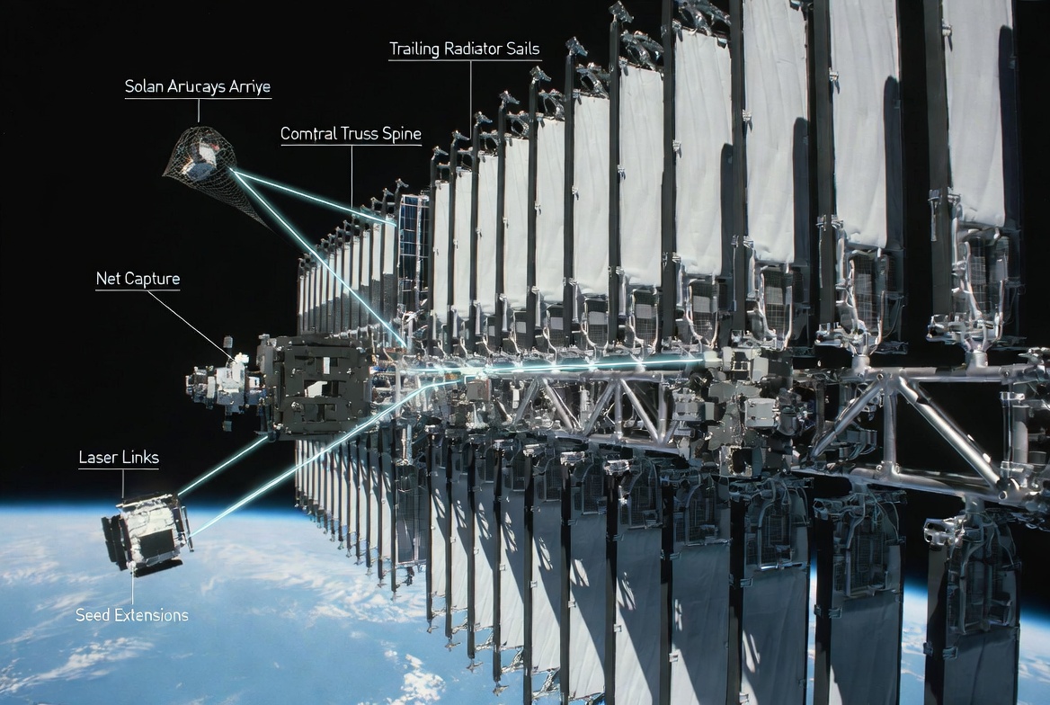
(Concept art attached: Updated visualization showing a mature grid at the 500–1,000 node scale with ~1,000 lb modules, correct labels, net capture, trailing radiator sails, laser links, and seed extensions.)
11

Kenny retweeted

And I’m gonna peg them both


2
41
366
4,200

para naman testigo sa pagkakatimbog ang peg natin today


9

I'm gonna peg him so hard he'll forget he's a man


1
1
10

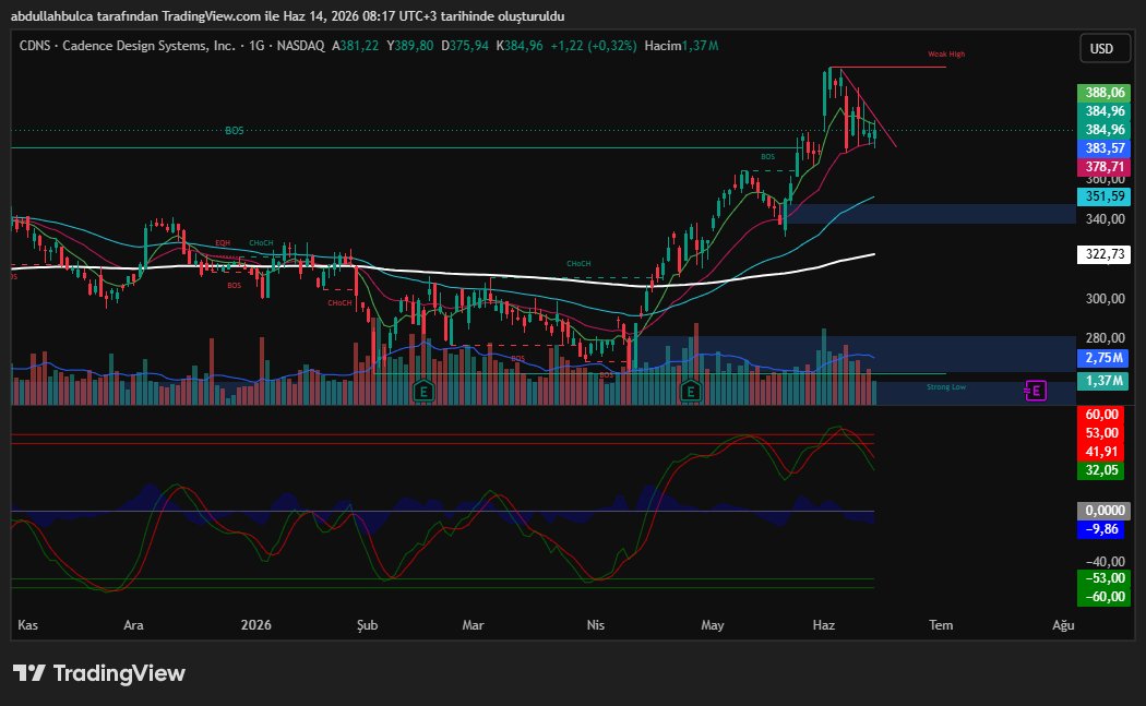
Son bilançoda büyüme rakamları çok güzel geldi. Chip tarafına talep geldikçe satışları lisanslamalar vs daha da büyüyecektir. Fakat asıl nokta PEG pahalı hale geldi. Daha gidebilir mi kesinlikle gidebilir ama ona göre riskininizi yönetmeniz gerekir. Teknik olarak iyi bir boğa bayrağı var 390$ kırabilirse eğer tekrar zirve yapmak isteyecektir. 374$ altına sarkarsa eğer 360$ ve 348$ test edebilir.
3

tang-in* gusto ata ikumpara sa Ms. Universe na know when to peak ang peg as an excuse.
Players are needed to perform as early as now so that in the Olympic qualifier games, they are ready.
Pabobo ng pabobo na lang argument.
1
1
7

To add to my comment, seeing Wemby at the postgame conference already showed that his ego has stepped down a peg. I respect that, and look forward to seeing him grow as a person and a player…he seemed in shock but ready to use this experience as self-reflection…I’m open-minded to potential change in his mindset. I don’t think he wants to become the most hated player in the league, so therefore he’ll adjust his attitude (hopefully) after summer to think about how he approached some of the games and plays. Until next season, #NBA fans!

Facts! But so glad that Wemby got put in his place and showed allllll 29 other fanbases who he really is with the dirty play. I hope he will reflect over the summer and realize that he needs to lose the ego and the intentional “hurting other players” shenanigans. Karma & true ethical hoops won the day, and s/o to Mike Brown formerly fired coach of the Kings now a f*cking championship coach of the Knicks!!
23

Indeed. I doubt it will happen. Instead someone will be sent to take me down a peg or two. She’s unlikely to do it herself. I’m beneath her.
2
Chap retweeted

Beg for the peg ! see the rest on my only fans - free to subscribe
onlyfans.com/obeyvalentina
🔥💋❤️
#azbdsm #mistressvvalentina
#prodominatrix #interacialcfnm
#2finefreaks #pegging #analwhore
#femdom #bdsmdungeon
2
6
43
4,951

Its a case of the lady doth protest too much. All the objection to it feels like trying to fit a square peg into a circle. The debate would be done long ago... really makes one wonder if the bottom really is the girl of the relationship - and what's so bad about that
33
Cassie Fleecington retweeted

2 Dec 2025

4
99
661
6,583


Because they're too busy glazing Israel and letting Israel peg them without lube.
7

If Katelyn doesn’t peg Hudson I’m sorry but she gotta start doing so or else I’ll take matters into my own hands
26