
Gas turbines | Audio engineering | Classics | BD at Rangeview
Joined November 2022
- Tweets 1,012
- Following 341
- Followers 1,041
- Likes 6,468
85 Photos and videos


Jun 10
Incredible things are happening

first check in. I am the investor now
2
214
Matt Walton retweeted

When I was learning to wrap my wrists for boxing, one very common reason I saw mentioned was that wrapping your knuckles a few extra turns was "padding" which made absolutely no sense to me. How is three layers of cotton supposed to cushion my knuckles??
Eventually I saw an in-depth video by an MMA coach explaining that the knuckle wrap is to hold the small bones of your hand in place. This helps prevent injury, and also helps you hit harder if your hand is "more like a glove full of rocks than a bag of jelly with some hard bits in it".
Aaaaahhhhhh, this makes way more sense to me. So why isn't this the common explanation?
This isn't apparent to anyone who hasn't both trained boxing AND also lacks experience punching people in the face without any gear on. In order for the old-timey boxing advice to make sense, you need extensive experience both within and outside of formal, geared up boxing.
If you are just some random soft hands modern person, you can gain extensive experience within the narrow discipline and still not have the breadth of experience to appreciate the wisdom of the old explanations.
A lot of old-timey wisdom is like this. The stated reason for doing something may or may not make any logical sense at all, and might even be utter nonsense. But the bigger picture is often that there's deep wisdom that only comes from deep and wide experience behind it.
It's just that the people passing on the wisdom were inarticulate (or even illiterate), and so they just made up some story to help it stick with the young knuckleheads they were trying to teach. Yeah yeah whatever kid, just do it ok.
A lot of things in sports, the physical, and the human mind are like this. Just because the old-timey wisdom makes no sense when you think about it for ten seconds doesn't mean it's bad advice. In fact it may be the opposite.
It's common for online smarty pants types to make a big deal about debunking old-timey wisdom based on this kind of logic. But logic is different than wisdom, and often inferior.
I've learned to distrust superficially logical explanations for any complicated phenomenon, and yes, punching people in the face is a surprisingly complicated phenomenon.
I see this trait of over reliance on logical consistency in midrange engineers, atheists, people just learning a trade/craft, sports neophytes, people who built their identity around being the smartest teenager in the room, and other habitual deboonker reddit types.
This is why the bell curve meme has such wide applicability. Very relatable. It can also be seen as illustrating a journey every thoughtful person has made. From credulous neophyte, to know-it-all midwit, to seasoned wisdom respecter.
Chestertons fence etc....

40
33
727
78,028
Jun 6
Niles King LeBlond

Cincinnati, Bridgeport, Hardinge…
1
117
Jun 4
I'm looking to hire a mechanical automation / equipment engineer at Rangeview. We need mechanical depth and agency. Experience in automation, controls, furnaces, vacuum systems, aerospace manufacturing, FSAE, or rocketry would be relevant and valuable.
If the idea of building the tools that rebuild American manufacturing sounds interesting, I'd love to talk.
1
2
4
771
Matt Walton retweeted

May 30
We need to build this supply chain ground up; instead of top down form integrators. We need massive industrial capacity that is focused on speed and flexibility! And let 1000s of small integrator teams come alive on top of this flexible industrial base! They will systems we never even thought of! More giant neo of legacy prime integrators are not the answer. We need to democratize being an integrator.
5
2
22
1,406
Matt Walton retweeted

May 26
C.S. Lewis, this is what life boils down to at the end of the day

24
831
5,807
206,000
Matt Walton retweeted

May 13
America doesn’t just need new weapons. It needs a new way to build them.
The bottleneck is no longer design. It’s manufacturing.
At the AI Expo in Washington, DC, @EdwardMehr made the case for a new kind of @DeptofWar prime: Modern manufacturing infrastructure built for speed, scale, and adaptability. 🇺🇸
1
8
28
3,556
Matt Walton retweeted

Apr 24
A reminder to all naval officers, sage advice from our first American naval hero - John Paul Jones:
Qualifications of a Naval Officer
"It is by no means enough that an officer of the Navy should be a capable mariner. He must be that, of course, but also a great deal more. He should be as well a gentleman of liberal education, refined manners, punctilious courtesy, and the nicest sense of personal honor.
He should be the soul of tact, patience, justice, firmness, kindness, and charity. No meritorious act of a subordinate should escape his attention or be left to pass without its reward, even if the reward is only a word of approval.
Conversely, he should not be blind to a single fault in any subordinate, though at the same time, he should be quick and unfailing to distinguish error from malice, thoughtlessness from incompetency, and well meant shortcomings from heedless or stupid blunder. In one word, every commander should keep constantly before him the great truth, that to be well obeyed, he must be perfectly esteemed."
--Compiled by Augustus C. Buell from letters written by John Paul Jones
9
44
292
13,009
Matt Walton retweeted

The shape appears compliated by the underlying principles and design goals are very simple, and can all be calulated with a pencil and paper.
1) Set your mass flow, at the atmospheric conditions you need the velocity into the compressor cant go above the speed of sound. This sets the minimum diameter of the entry.
2) Set your desired outlet pressure, this is determined by the radius of the disc and the size/efficiency of the volute available. You can work this out from Eulers turbomachinery equation, derived in the year 1752.
You can start with just multiplying the tip speed by the tangential velocity of the air leaving the rotor tip.
3) Whats the maximum acceptable temperature rise ?
The temperature rise through the compressor goes up with the square of the tip speed. This (among other things) allows you to set a ceiling for the shaft speed.
4) Knowing all this, and your basic adabatic equation (whats the temperature of air after you squish it by a certain amount), you can then do the bit thats so simple people often forget about it. Area ruling, the velocity through the compressor wants to be constant, since its density and temperature change, you need to design the flow channels so that as these variables change, the area changes to keep the velocity constant. This keeps turblence low and improves efficiency.
In the Second World War all this was done by hand, and to speed it it, nomograms were made to quickly cross reference the characteristics to check the key dimensions.
There is a lot more to it, but the basic ingredients are all very straightforward.
Here is Bruno Eckerts WW2 German compressor design nomogram, onto which I`ve added how you draw the lines (Had is adiabatic head, which is what the German compressor designers used instead of Pressure Ratio, of "reasons"*)
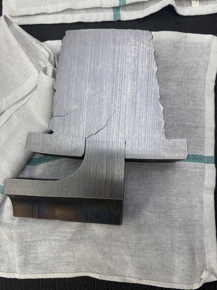
Photo is a German aeroplane engine compressor, in mid-manufacture stage before the inducer vanes are cold-bent, this is the raw forging. The only really significant advance is the forward lean to the blades, which helps lower tip leakage and also helps prevent blade resonance by buttressing the blades as "beam" elements.
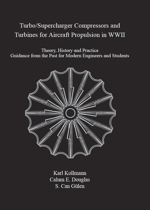
* See my translation of the German engineering professors (Prof. Dr.-Ing Kollmann), book on WW2 compressor design published by the American Society of Mechanical Engineers for more end-boss level geek details. I found his original typewritten manuscript in a house in Stuttgart, which I then translated and published with ASME with much aid from world renowned compressor expert Dr Gülen who really assisted a lot by putting in the mathematical bridging between the WW2 theory and contemporary practise.


Apr 24

centrifugal impellers are truly one of those crazy things that just looks alien too me
every curve on the part is solving something. the blade twist, the backsweep, the fillet blending into the hub, the passage narrowing toward the tip.
and somehow the result is just *chef's kiss*. form is just physics that got resolved.

13
87
871
54,453
Matt Walton retweeted

Apr 23
it sounds kinda like CCCHHCHHHSSSHSSHSHSHSHHHSh
1
1
22
733
Matt Walton retweeted

Apr 23
The dumbest and easiest management trick in the book is to just be super positive and encouraging all the time. It really does help, it requires 0 brain cells, and so few people do it that it really stands out. I cannot express just how well this one dumb trick works.
24
170
4,241
92,874
Matt Walton retweeted

Apr 21
A classic, rebuilt with a modern spin.
The #GEAerospaceCrew at our Lynn facility recently brought back the legendary “Turbo Town” sign. Originally installed in 1964 to celebrate the “Birthplace of the American Jet Engine,” the iconic sign has been reimagined for today — honoring a legacy that began with America’s first jet engine in 1942.
Learn more about the installation here 🔗 bit.ly/4coCo3x

27
203
2,186
166,502
Matt Walton retweeted

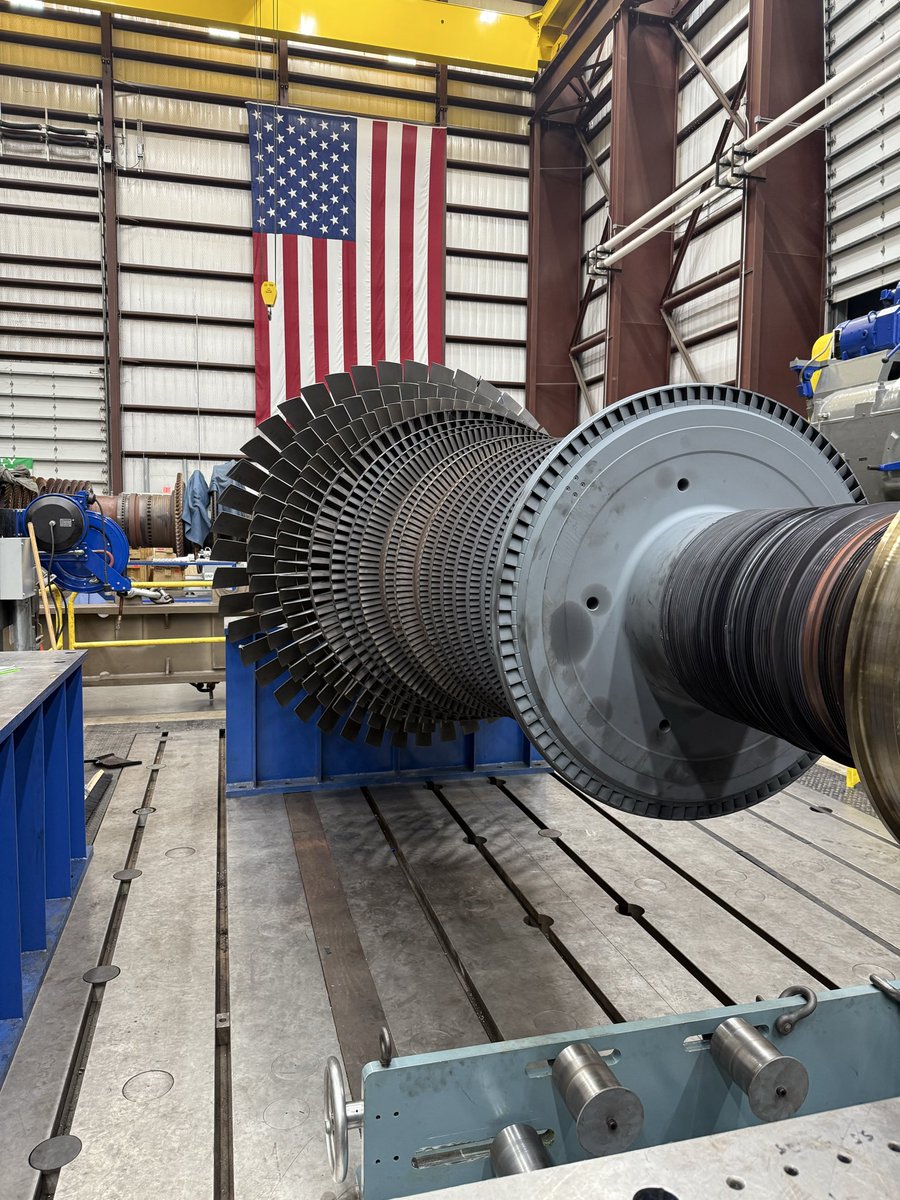
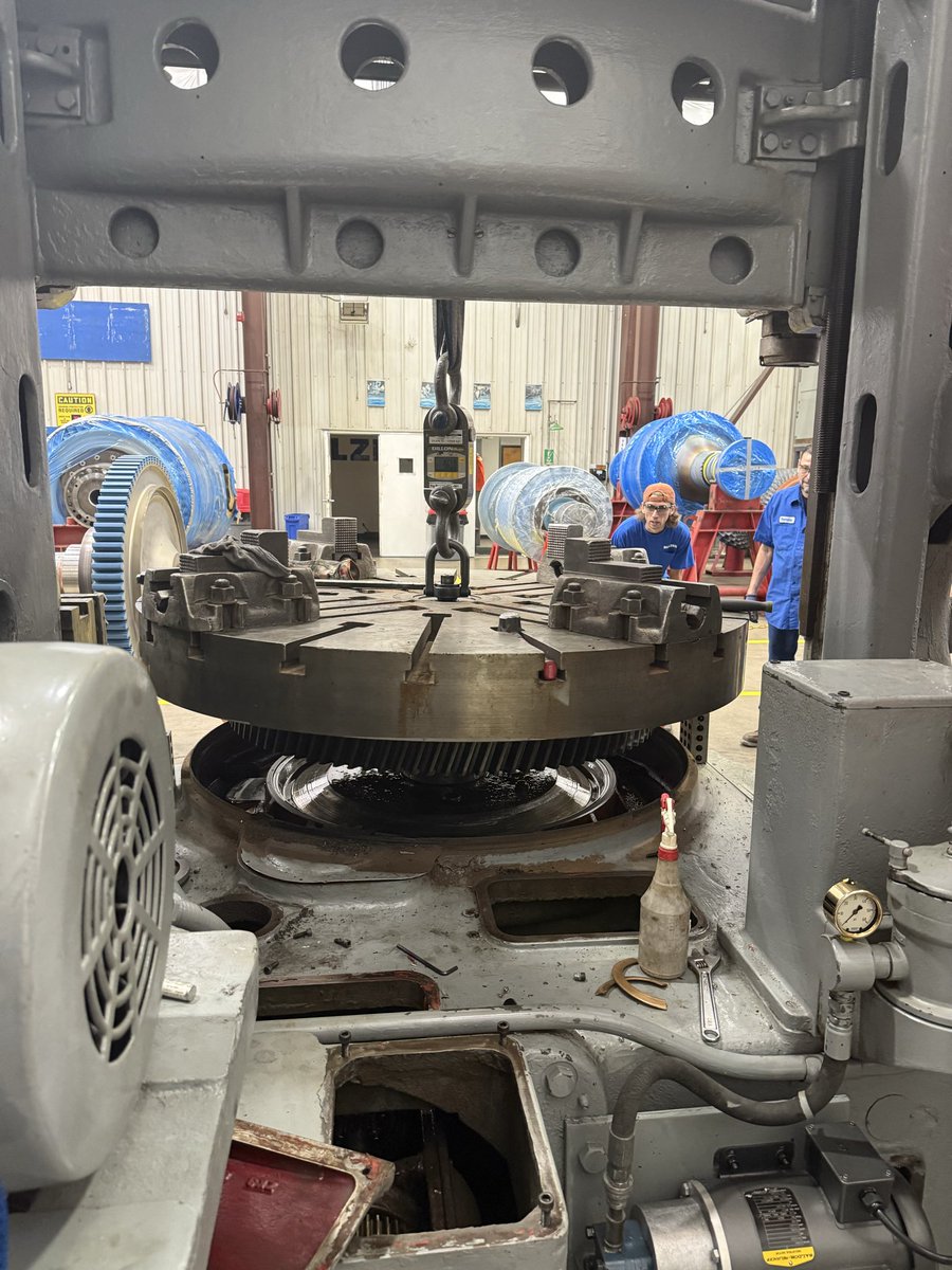
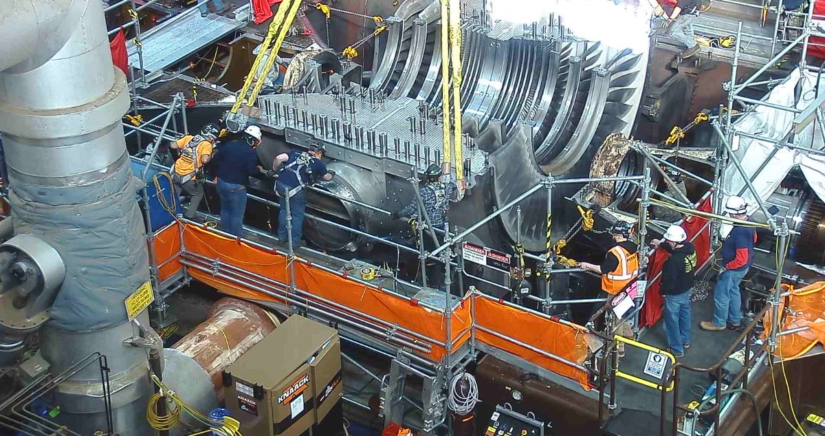
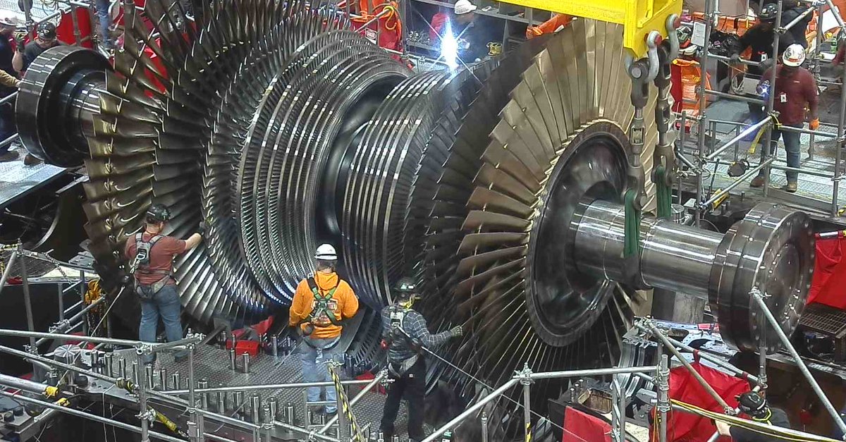
Behind-the-scenes look at the turbine replacement work during Byron Clean Energy Center’s recent refueling and maintenance outage. Part of the $800M investment at our Byron and Braidwood sites in Illinois to add approximately 158 MW of reliable, emissions-free power to the grid.

4
15
109
15,272
Matt Walton retweeted

Apr 17
The Cato Institute implies the existence of a Caesar Institute.
47
150
2,472
228,428
Matt Walton retweeted

Apr 1
Venture capital, for all its ability to drive innovation, is mismatched with many of the technologies civilization needs most:
- Building a nuclear reactor costs billions and takes over a decade.
- Bringing a new cancer drug to market requires $1-2 billion over ten to fifteen years, with a 90% failure rate.
- An estimated 80% of energy startups fail because funding dries up during the scaling phase.
Meanwhile, the biggest VC firms are pouring record funding into AI, crypto or whatever the latest thing is. I am not pointing fingers - the time horizons for exit, incentives and LP demands drive this behaviour - but we are leaving critical opportunities to drive human progress underfunded.
A growing body of research proposes three roles for the state to help bridge this gap:
First, acting as a limited partner for emerging fund managers, where studies show moving public LP activity earlier produces the same productivity gains as doubling the allocation.
Second, funding self-sustaining "venture philanthropy" vehicles that make small, broad investments in university spin-outs, accepting that over 96% will fail while the outliers more than cover losses.
Third, guaranteeing junior tranches in securitized "megafunds" that pool hundreds of R&D projects into bond-like instruments accessible to pension funds and insurers, unlocking debt markets 400 times larger than VC.
Read the full breakdown below from @credistick on the research that underpins these strategies.
13
35
212
30,990
Matt Walton retweeted

Mar 23
Kicking off a new blog. Have had too many takes over the past year, it’s time to set them free.
First up: manufacturing discourse skips a fundamental detail: knowledge is implicitly stored in the factory and tuned by de-facto reinforcement learning.
darkmatter.blog/articles/dar…
16
51
478
78,017