
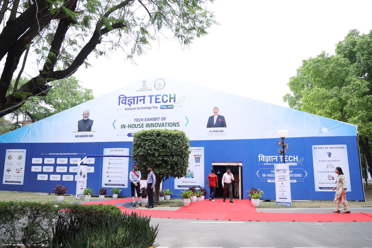
On the occasion of National Technology Day 2026, National Institute of Pharmaceutical Education and Research Mohali, National Institute of Pharmaceutical Education and Research Raebareli, and National Institute of Pharmaceutical Education and Research Hyderabad and National Institute of Pharmaceutical Education and Research, Kolkata showcased cutting-edge indigenous technologies in biotechnology, advanced drug delivery, green chemistry, neuroprotective therapeutics, nanotechnology, and rapid diagnostics at the exhibition organised by
@DBTIndia in New Delhi as part of the Vigyan TECH 2026 celebrations. The exhibition was inaugurated by Hon’ble Minister of State Dr. Jitendra Singh.
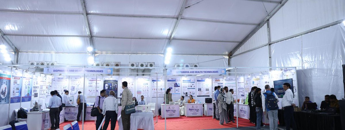
The innovations included a novel bispecific antibody platform, Direct Powder Extrusion (DPE) technology, green synthesis approaches for neuroprotective compounds, sustainable catalytic processes with industrial scale-up potential, advanced dendrimer and plant exosome-based drug delivery systems, rapid sepsis diagnostics for critical care applications, and industry-transferred fluorescent probe technologies for biomedical imaging and disease diagnostics. These technologies highlight India’s growing strength in translational research and their potential impact across healthcare, pharmaceuticals, biotechnology, and diagnostics, reinforcing the vision of #AtmanirbharBharat through affordable and scalable innovation.
➡️NIPER, Mohali showcased advanced technologies including “BiSpekDAb”, a novel bispecific antibody platform, and “SingleStep Direct Powder Extrusion (DPE)” technology for pharmaceutical applications.
➡️ NIPER, Raebareli presented innovative technologies in neuroprotective therapeutics and green chemistry. The showcased innovations included a catalyst-free green synthesis approach for Kynurenic Acid derivatives with neuroprotective potential, sustainable annulation technologies for industrial translation, advanced dendrimer-based targeted drug delivery systems, and plant exosome-based nanotechnology for diagnostics and therapeutics.
#विज्ञानTech2026 #NationalTechnologyDay #राष्ट्रीयप्रौद्योगिकीदिवस #ViksitBharat

3
3
10
583

Apr 13
@PMOIndia @HMOIndia @BJP4India @RSSorg not bothered as well fooling Hindus with #sabkasaathvikaas delusion 12 yrs yet not a singlestep taken to protect Hindus interests instead playing a new level of appeasement politics beating conigs too #kuchbhi @RatanSharda55 @ARanganathan72
2
7
395

Mar 23
Zrovna Z80 udělal docela dobře, ale je pravda, že nezačínal od nuly. A hodně pomohly právě ty referenční testovací sady z FUSE a SingleStep. Ty si hezky spouští, kontroluje výsledky a opravuje kód, a v Autoresearch smyčce mu to jde jedna báseň!
4
311

23 Nov 2025
4
125

5 Oct 2025
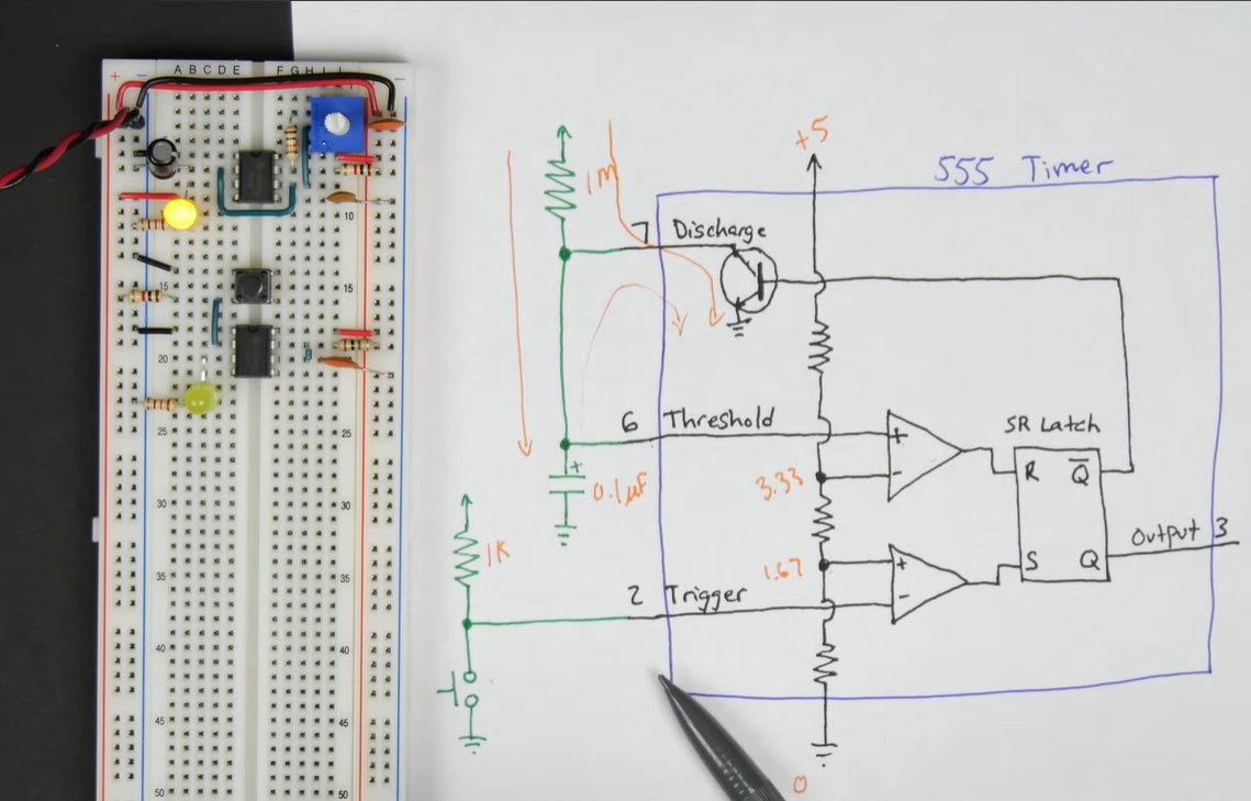
Day 2 of my 8bit Breadboard Computer Build!
today, I assembled and tested the monostable 555 timer circuit, which serves as the manual clock pulse generator, allowing me to advance the CPU one step at a time, unlike the astable mode I built on day 1 (which continuously oscillates), the monostable mode produces a single pulse each time it’s triggered, this pulse acts as a single “tick” of the computer’s clock, letting me observe each instruction or logic operation manually, an essential feature when debugging the early stages of a CPU, here’s how it works fundamentally: when the trigger pin (pin 2) receives a low pulse, it causes the output (pin 3) to go high for a fixed duration, determined by the resistor (R) and capacitor (C) connected to pins 6 and 7, the timing period is calculated using the formula:
T = 1.1 × R × C
during this time, the capacitor charges through the resistor until it reaches 2/3 of the supply voltage, at which point the internal comparator resets the flipflop and brings the output low again, to ensure stable operation, I used a debounced push button for the trigger, along with decoupling capacitors across the power lines to suppress noise and prevent false triggering, the output LED visually represents the clock pulse width, lighting up each time the circuit is triggered, with this, I now have both modes of clock control:
Astable Clock → Continuous automatic clock.
Monostable Clock → Manual singlestep control.
this gives me full control over the timing of my computer, allowing precise debugging as I move toward building the registers and ALU next.
2
109

27 May 2025
Electroniq WIP. New debugger feature coming soon. Jump from breakpoint to breakpoint or singlestep through your 6502 source code, all while drawing over the previous PAL field and showing the exact position of the 'electron beam' in the current PAL field ( hblank and vblank)
4
5
35
977

12 May 2025
Every #business began with a #singlestep. The journey to #financialempowerment starts with action.
This week, we're diving into the world of #financing. Stay tuned for #dailyinsights to guide you on securing the right funding.
#EnablingEntrepreneurs #MondayMotivation
1
4
450

10 May 2025
Feels like the combination of singlestep transfers, pizzaswap on mainnet, 2.0 smart contracts, and stablecoins is almost enough to bring back a new Brc-20 season.
But.
We also need wrapped Btc on Brc-20.
Then EVERYTHING changes.
1
7
539

22 Apr 2025
@union_build is revolutionizing blockchain interoperability Direct Connections enable singlestep, trustless crosschain transfers. Recursive Connections leverage statelenses for multihop message passing in complex networks. Built on IBC , ZKproofs for speed, security #union_build
1
3
31

19 Apr 2025
ステステやばい色々思い出しちゃうあの頃はキツかった😭NiziUに救われてたって改めて思い出すデビュー1600日。ひとりカラオケで掛け声練習してた時「レッツゴー」で嗚咽してたのも思い出した🤣 黒歴史だわw
NiziU(니쥬) Debut SingleStep and a step
一緒に思い出そ👉 youtu.be/a6QT0acJFQE?si=aXwn…
1
12
615

16 Apr 2025
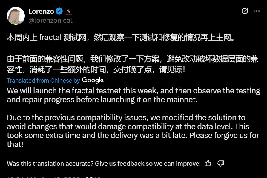
#BRC20 single step transfer to launch on fractal testnet this week! 👀🔥
$ORDI BRC2.0 #SingleStep L1 token transfers coming
1
8
1,288

Cyber Apocalypse CTF 2025 の Singlestep は gdb-python で無理やり実行コードを抽出したのですが、Writeup で見た Unicorn と Capstone を使用した自己復元型バイナリの難読化解除手法がスマートで参考になったのでまとめてみました。
kashiwaba-yuki.com/unicorn-b…
7
44
2,792

4 Feb 2025
A journey of 1000 miles begins with a single step. Go take that first step. ❤️
#journey #SingleStep #YouCanDoIt #read #novels #indieauthor #fictionbooks #kyonajiles

1
1
4
60

14 Aug 2024
single stepping my ios app on device, takes about 10 seconds for every singlestep. this is not normal right?
2
4
952


30 Nov 2023
People who are confident don't hesitate to engage in uncomfortable activities. They don't allow fear to hold them back from accomplishing specific goals. #confidence #singlestep #engage #life

1
78

20 Aug 2023
Sampler name abbreviations: #stablediffusion
✅ Karras = sampler is using a specific type of noise
✅ DPM the improved sampler of DDIM
✅ DPM has different modes, S (singlestep), M (multistep)
✅ 2 = second-order
✅ DPM 2M = second-order multistep sampler
1
2
1,192

27 Jul 2023
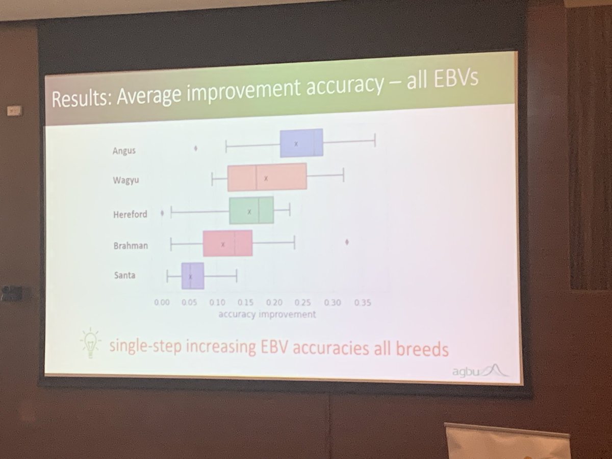
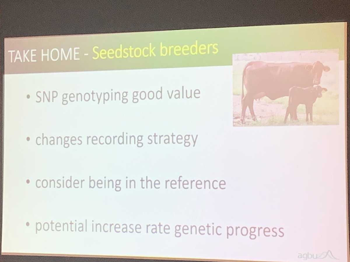
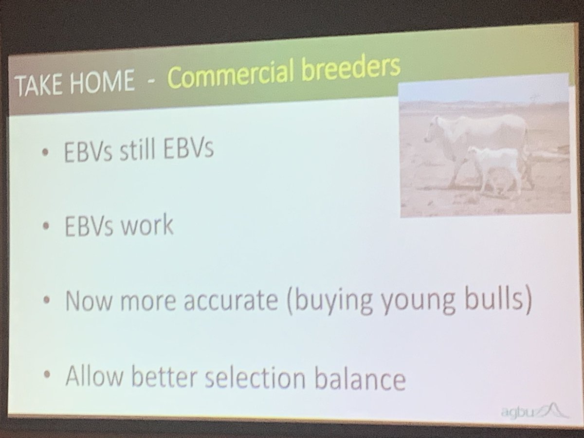
👨🌾 Exciting stuff from David Johnston of @agbu_gene! He's shining a spotlight on the latest singlestep evaluations in the breedplan system. 🐄📈 The insights are gold for all industry sectors at #aaabg2023! 🌱
@meatlivestock @UniNewEngland @nswdpi

7
264

20 Jul 2023
@ActorLeeMinHo Lee MinHo,I read InterviewYourAnswerTouchedMySoulWhyIsThat?BecausetheLong JourneyStartsWith A SingleStep NotEveryoneRealizesThisButYouDoYouHaveReached A Very Beautiful DimensionByLevelingUpOnThePathFromRawnessToMaturtyKnowingYourselfBeginningOfAllWisdom👍WeLoveYou


1
1
12
269

5 Jul 2023
Why do #unicorns like silly #jokes? Because they’re uni-corny. Why will you like SingleStep Laser Transfer Paper? Because it only transfers the toner, not the background film! Visit rhinotechinc.com 🦏
#screenprintinglife #screenprintingshop #printlife #heattransfer
2
6
143