
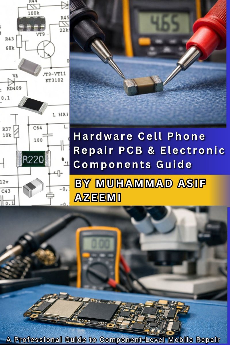
🆕Exciting News! I'm thrilled to share that my book📖 "Hardware Cell Phone Repair PCB & Electronic Components Guide" is now available on Amazon!🚀Grab your copy now🙂#smartphonerepair #electroniccomponent #testandmeasurement #PCBlayers #amazonkindle👉 amazon.com/dp/B0GCNPRD8F

ALT Cell Phone PCB Hardware Repair tips
4
30
🆕Exciting News! I'm thrilled to share that my book📖 "Hardware Cell Phone Repair PCB & Electronic Components Guide" is now available on Amazon!🚀Grab your copy now🙂#smartphonerepair #electroniccomponent #testandmeasurement #PCBlayers #amazonkindle👉 amazon.com/dp/B0GCNPRD8F

ALT Cell Phone PCB Hardware Repair tips
2
17
🆕Exciting News! I'm thrilled to share that my book📖 "Hardware Cell Phone Repair PCB & Electronic Components Guide" is now available on Amazon!🚀Grab your copy now🙂#smartphonerepair #electroniccomponent #testandmeasurement #PCBlayers #amazonkindle👉 amazon.com/dp/B0GCNPRD8F

ALT Cell Phone PCB Hardware Repair tips
1
5
34
🆕Exciting News! I'm thrilled to share that my book📖 "Hardware Cell Phone Repair PCB & Electronic Components Guide" is now available on Amazon!🚀Grab your copy now🙂#cellphonerepair #electroniccomponent #testandmeasurement #PCBlayers #amazonkindle👉 amazon.com/dp/B0GCNPRD8F
ALT Cell Phone PCB Hardware Repair tips
2
17
🆕Exciting News! I'm thrilled to share that my book📖 "Hardware Cell Phone Repair PCB & Electronic Components Guide" is now available on Amazon!🚀Grab your copy now🙂#cellphonerepair #PCB #electroniccomponent #testandmeasurement #phonerepair #amazonkindle👉amazon.com/dp/B0GCNPRD8F
1
2
48

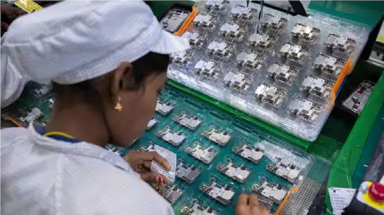
ரூ.41,863 கோடி முதலீட்டில் 22 மின்னணு உதிரிபாக உற்பத்தி திட்டத்துக்கு ஒப்புதல்
#India | #ElectronicComponent
hindutamil.in/news/business/…
1
605

13 Oct 2025
The moment when the chip goes through reflow soldering #SMT #ADI #MLCC #Chips #electroniccomponent #PCBA #ICGOODFIND
2
35
25 Sep 2025
PCBA Chip Desoldering and Soldering Techniques
#PCBA #ChipRework #DesolderingSkills #ElectronicsRepair #electronics #electroniccomponent #icgoodfind
2
7

18 Jun 2025
Teardown of a Chip: Exploring the NE555
#ic #chip #electroniccomponent #ne555 #pcbmanufacturing #pcb
#electronics #hardware #electronicengineering #iot #engineering
2
2
88

5 Jun 2025
World Environment Day 🌍
#IndusTechnologies #ElectronicComponent #WorldEnvironmentDay #GoGreen #EcoFriendly #SustainableTechnology #ReduceEWaste #GreenElectronics

1
3
16
22 May 2025
How to trim capacitor components for PCB assembly manufacturing
#capacitor #electroniccomponent #pcbassembly #smt #pcba #pcb
#electronicmanufacturing #electronicengineering #electronics
1
4
89

28 Mar 2025
#Business | Cabinet approves electronic component manufacturing PLI scheme at outlay of Rs 22,919 crore 💰
Find out more ⤵️
moneycontrol.com/news/busine…
#Cabinet #ElectronicComponent #PLIScheme
3
7
1,878

30 Nov 2024
How much do you know about connecting resistor tolerances? #ElectronicComponent #Electronic #Capacitor #pcb #Resistor #diyproject
1
102

27 Nov 2024
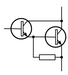
Darlington ease emitter bypass resistor
Although the Darlington pair circuit is often used in its basic format, it is often seen with a bypass resistor between the base and emitter connections of the final transistor.
The bypass resistor is included to aid the switch-off process. Without the resistor in place, there is no discharge path for any charge held in the capacitor formed by the base emitter junction. Including it enables the charge stored in this capacitor to dissipate and this aids a faster turn-off.
It is good design to include this resistor, but if speed is not an issue then the resistor can be omitted. However, unless cost and component count are key drivers within the circuit design, then it is wise to include this electroniccomponent to provent any unusual turn-off phenomena.
Determining the resistor value is not an exact science. Smaller resistors will give a faster turn-off, but if they are made too small then a large proportion of the drive current for the second transistor passes through the resistor and gain is lost.
If the value of the resistor is low and it robs current from the base of the second transistor, then current gain will be reduced and the equation for the overall gain of the Darlington will need to accommdate this.
Typical values might be a few hundred Ohms for a power Darlington transistor and a few thousand Ohms for a small current transistor.
1
22
683

25 Oct 2024
In the spirit of the spooky season, we're diving into the terrifying world of obsolescence and how it can haunt your production. 😱 #Obsolescence #SupplyChain #HalloweenHorror #electroniccomponent #Procurement #AmpleSolutions
ampleglobal.com/sourcing-and…
1
2
60
10 Oct 2024
4
6
94

27 Sep 2024
🎉Congratulations to The #ElectronicComponent Show #Oxford2024 for a successful event!
Did everyone catch a glimpse of the custom PCBWay bird mugs?
🥰Looking forward to seeing you all next time!
#ECS


2
8
894
30 Aug 2024
#W25Q16JWSNIQ #SOP8 #WINBOND #FLASH #W25Q256JWEIQ #BGA #QX2305 #sensor #chip #electroniccomponent #integratedcircuit #electronichardware #electronics #IC #icgoodfind Skype: sales@icgoodfind.com icgoodfind.com
2
33

1 Jul 2024
Choosing the right embedded chip is crucial. Key indicators include clock speed, core count, RAM size, power consumption, and security features. Read our guide to enhance your design!
#EmbeddedSystems #TechTips #PerformanceEvaluation #semiconductors #ElectronicComponent

2
24

26 Jun 2024
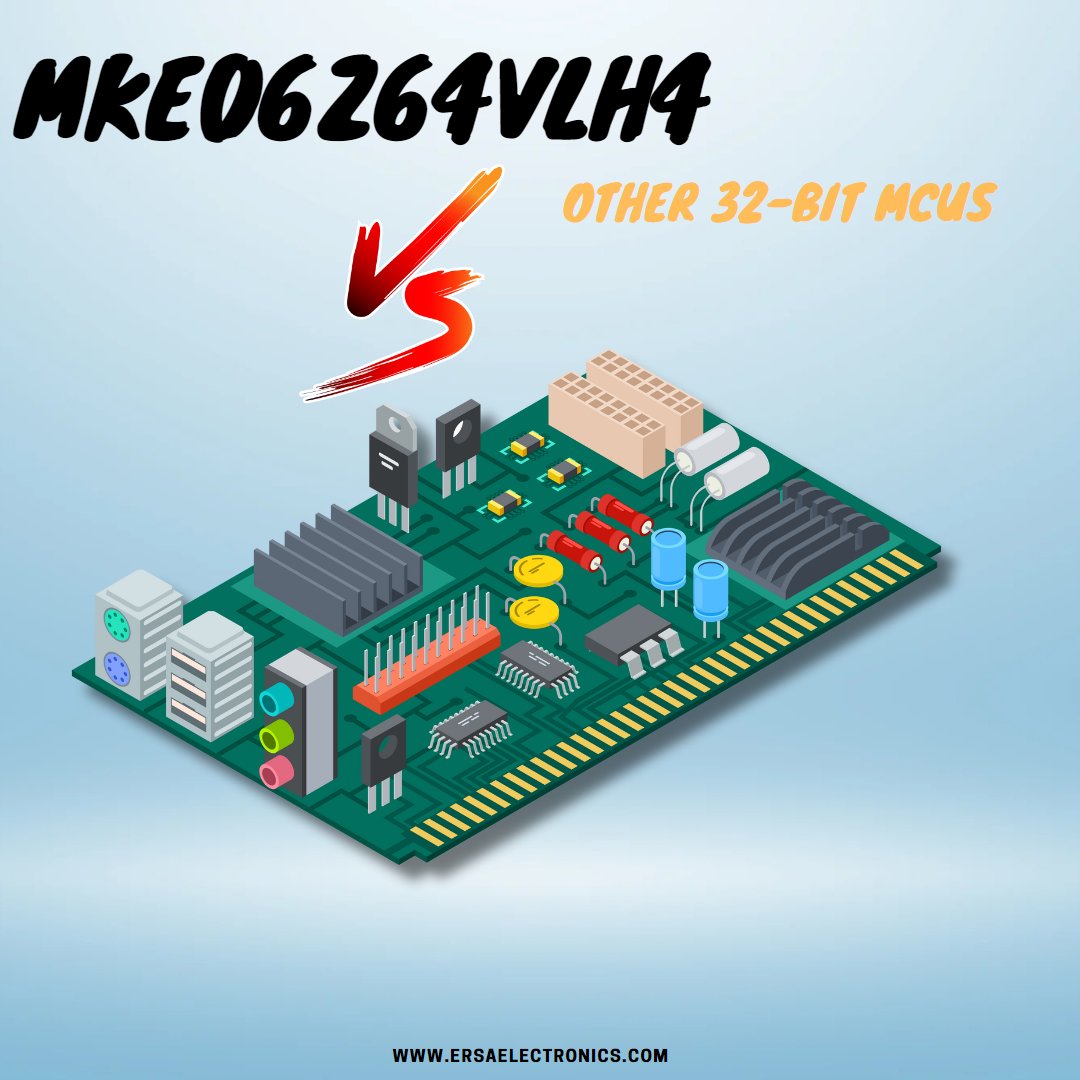
Explore the detailed comparison of MKE06Z64VLH4 vs other 32-bit MCUs! Find out which MCU suits your needs best. Visit Ersa Electronics' blog now
Read More: ersaelectronics.com/blog/mke…
#semiconductor #integratedcircuit #ElectronicComponent #MCU #TechComparison
2
16