
Are Carbon Composition Resisters Used These Days?
Carbon composition resistors may seem like totally outdated technology but it may surprise you to know they are still incorporated into new designs for very good reasons.
The Basics:
Carbon composition resistors were among the first resistors widely used in electronic circuits. They're made from a mixture of carbon dust or graphite and a non-conductive ceramic (like clay) binder. This mixture is molded into a cylindrical shape, with wire leads attached at each end for connection in circuits.
The resistance is primarily determined by the ratio of carbon to ceramic - more carbon means lower resistance.
Characteristics:
- Tolerance: Typically, these resistors have a tolerance of around 5% to 20%, which was quite standard before precision components became widely available. 20% was the standard!
- Temperature Coefficient: One of the drawbacks is their relatively high temperature coefficient, meaning their resistance can vary significantly with temperature changes.
- Noise: They can be much noisier than modern types like metal film resistors, due to the carbon particles not providing a uniform path for electrons, which leads to thermal noise.
Applications:
Despite these characteristics, carbon composition resistors shine in specific areas:
- High Voltage Applications: They tend to handle high voltage spikes better than some modern resistor types, making them valuable in scenarios where component reliability under electrical stress is crucial.
- Audio Equipment: Their unique noise characteristics are occasionally preferred in audio circuits for vintage or warm sound reproduction. Some audiophiles swear by the "sound" of carbon composition resistors in certain applications.
- Pulse Applications: Their ability to absorb energy without breakdown makes them ideal for circuits where sharp, high-energy pulses are common. This last point is the largest use in design for current equipment.
Manufacturing & Availability:
While less common than before due to the dominance of film resistors, carbon composition resistors are still manufactured by a few companies, mainly for specialized applications or for those seeking the old-school vibe in their electronics projects.
Considerations:
These resistors are known to significantly change their value over long periods of time, especially when subjected to heat. Old resistors in vintage radios are commonly found to change their resistance by 50% and more.
For more information check out the link I’ll post shortly in the comments.
Have you used carbon composition resistors recently for some specialist application, or do you always avoid them at all costs?
#resistors #carboncomposition #electroniccomponents #electronicsnotes

1
1
2
27
The "GaN vs. SiC" debate in power electronics is one of the most significant shifts in modern hardware design.
As we move away from traditional silicon, choosing between Gallium Nitride (GaN) and Silicon Carbide (SiC) is no longer a competition—it is a strategic decision driven by physics.
Both are "wide-bandgap" (WBG) materials, but they excel in different territories.
The Fundamental Split:
* Gallium Nitride (GaN): The Speed Demon. GaN features superior electron mobility, allowing for incredibly fast switching—often in the MHz range. Because it has no "body diode" (and therefore no reverse recovery charge), it is the cleanest switcher for high-frequency, ultra-compact applications. It dominates the sub-650V space, like laptop adapters and 5G infrastructure.
* Silicon Carbide (SiC): The Powerhouse. SiC leads in thermal conductivity and high-voltage handling. It thrives where the heat is intense and the voltage levels are massive (650V to 1,700V ). This makes SiC the "undisputed champion" for EV traction inverters, solar grid inverters, and heavy industrial motor drives.
The Overall Takeaway
It’s not about which material is "better"—it’s about matching the physics to the design constraint:
* If your design priority is size, frequency, and portability, GaN is your answer.
* If your design priority is thermal performance, reliability under extreme load, and high-voltage power, SiC is the king.
As these technologies mature, we are seeing a partnership where designs increasingly leverage the strengths of both rather than trying to force one material to do it all.
Want to dive deeper into the technical characteristics and application-specific nuances?
Check out the full breakdown on Electronics Notes: electronics-notes.com/articl…
#PowerElectronics #WideBandgap #GaN #SiC #Engineering #Semiconductors #HardwareDesign #Innovation #Efficiency #electronicsnotes

4
22
466
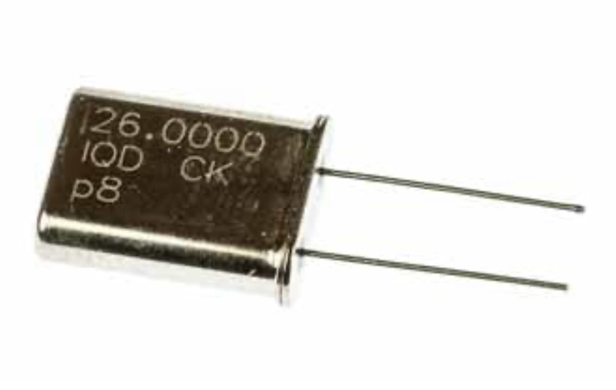
How to Specify a Quartz Crystal
Specifying a quartz crystal involves a number of parameters that are not used with other components and may be very unfamiliar.
Based on the guide from Electronics Notes, here is the essential checklist for specifying a crystal resonator that ensures reliability and precision.
1. Nominal Frequency & Mode
It’s standard to specify frequency to six decimal places (e.g., 25.000000 MHz). But don’t forget the Mode:
• Fundamental: Typical for frequencies up to ~30 MHz.
• Overtone: Used for higher frequencies (3rd, 5th, or 7th overtone).
2. Resonance Mode & Load Capacitance (CL)
This is the most common area for errors.
• Series vs. Parallel: Most modern ICs use parallel resonance.
• CL is key: This is the capacitance the crystal "sees" from your circuit. If your crystal is rated for 10pF but your circuit provides 20pF, your frequency will shift (pull).
3. Frequency Tolerance & Stability
• Tolerance: The allowable deviation at 25°C (usually ±10 to ±50 ppm).
• Stability: How much the frequency drifts over the Operating Temperature Range (e.g., -40°C to 85°C).
4. ESR (Equivalent Series Resistance)
As packages get smaller, ESR tends to go up. If ESR is too high, your oscillator might not start. Always check that your IC’s gain can overcome the crystal's maximum ESR.
5. Drive Level (DL)
This is the power dissipated in the crystal (measured in µW). Over-driving a tiny SMD crystal can cause "frequency jumps" or even physical damage to the quartz blank.
6. Ageing
Crystals change frequency over time, usually following a logarithmic curve. A typical spec is ±3 ppm for the first year.
The Specification Checklist:
When ordering or searching a datasheet, make sure you have these 9 points covered:
✅ Frequency (MHz)
✅ Mode (Fundamental/Overtone)
✅ Load Capacitance (CL in pF)
✅ Frequency Tolerance (ppm @ 25°C)
✅ Frequency Stability (ppm over Temp)
✅ Operating Temp Range (°C)
✅ Max ESR (Ohms)
✅ Max Drive Level (µW)
✅ Package Style (e.g., SMD 3225)
Getting these right at the start prevents "hidden" bugs that only show up in mass production or extreme temperatures!
More details in the link in the comments.
#ElectronicsEngineering #CircuitDesign #HardwareDesign #electroniccomponents #PCBDesign #EngineeringTips #electronicsnotes
2
25
910
How Does a Digital Multimeter Work? - Understand the Essentials.
Have you ever wondered what’s actually happening inside your Digital Multimeter (DMM) when you probe a circuit?
While it looks like a simple digital screen replacing an old analogue needle, the "magic" inside is a fascinating process of high-speed translation.
Based on the expert insights from Electronics Notes, here is a breakdown of how your DMM actually works:
1. The Core: The ADC (Analog-to-Digital Converter)
The heart of every DMM is the ADC. Most general-purpose multimeters use a Successive Approximation Register (SAR).
• Think of it like a game of "Higher or Lower."
• The ADC compares the input voltage to a reference voltage, starting at half-scale and narrowing it down bit-by-bit until it "homes in" on the exact value.
2. Signal Pre-Conditioning
The ADC can only handle a specific, small range of voltage. To measure different things, the DMM "prepares" the signal:
• Voltage: Uses potential divider networks to scale high voltages down to a range the ADC can handle.
• Current: Measures the voltage drop across a known internal resistor (a shunt) and then calculates the current using Ohm’s Law.
• Resistance: Passes a small, known current through the component and measures the resulting voltage drop.
3. Buffering and Averaging
Ever notice why the numbers don’t jump around frantically? The DMM doesn't just show one raw sample. It buffers and averages multiple samples to filter out electrical noise, ensuring the reading you see on the LCD is stable and accurate.
4. The "Settling Time" Factor
When you switch ranges or probes, the internal circuitry needs time to stabilize. This is why the reading might "climb" for a split second before staying still. High-end meters also perform an Auto-Zero to ensure there’s no offset error before giving you the final result.
Pro Tip: Understanding this process helps you realize why "settling time" matters—especially when using computer-controlled test equipment where timing is everything!
🔗 For a full explanation, check the link to my website in the comments.
#Electronics #Engineering #TestEquipment #DigitalMultimeter #EmbeddedSystems #LearningElectronics #electronicsnotes

1
2
44
1,411
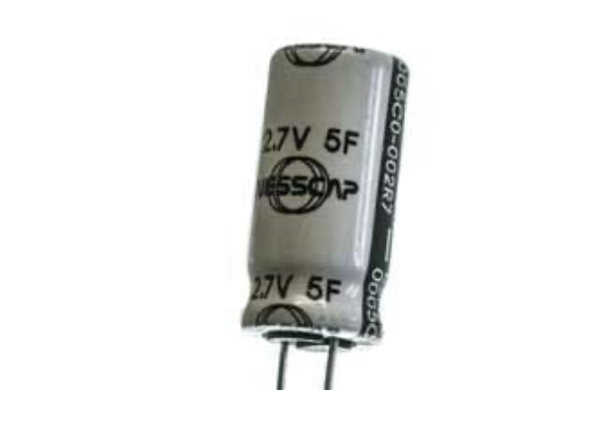
Which is better for your design: a Supercapacitor or a Battery?
As electronics technology advances, the line between these two energy storage giants is blurring. While they both store charge, their internal "DNA" is completely different.
Based on the insights from Electronics Notes, here is a breakdown of how they stack up against each other:
Supercapacitors: The Sprinters
Supercapacitors (or ultracapacitors) store energy electrostatically. Think of them as high-speed delivery vehicles.
* High Power Density: They can dump or absorb massive amounts of energy almost instantly.
* Fast Charging: They charge in seconds, not hours.
* Infinite Stamina: They can handle hundreds of thousands of charge-discharge cycles without breaking a sweat.
* The Trade-off: They have a comparatively low energy density and they can't hold a charge for a long duration.
Batteries: The Marathon Runners
Batteries store energy chemically. They are the long-haul tankers of the electronics world.
* High Energy Density: They excel at storing large amounts of energy in a small footprint, powering devices for hours or days.
* Steady Delivery: Great for sustained power, but slower to charge and discharge.
* Limited Lifespan: Chemical reactions degrade over time, leading to a limited number of cycles (typically hundreds to a few thousand).
The Best of Both Worlds: Hybrid Solutions
Why choose one when you can use both? We are seeing a massive rise in hybrid systems. By combining them, engineers get:
* Regenerative Braking in EVs: Supercaps capture the sudden burst of energy from braking, while batteries store it for the long drive.
* Peak Power Shaving: In smartphones, supercaps handle high-drain tasks like camera flashes, protecting the battery's longevity.
Whether you are designing for the grid, an EV, or a handheld gadget, understanding these trade-offs is key to system efficiency.
#Electronics #Engineering #EnergyStorage #Supercapacitors #Batteries #EV #TechTrends #electroniccomponents #electronicsnotes
2
4
27
1,538
Fascinating & Important Facts You Need to Know about Zener Diodes
Did you know that the "Zener Diode" is technically a bit of a misnomer for most of the voltage regulator diodes we use today?
Based on my the page in my Electronics Notes website about this everyday component, there are some truly curious facts that every engineer and tech enthusiast should know:
🔹 The "Magic" Number is 5.5V
Most people call them all "Zener diodes," but there are actually two different physical effects at play. Below ~5.5V, the Zener effect dominates. Above ~5.5V, a process called Impact Ionization (Avalanche breakdown) progressively takes over.
🔹 Temperature Stability Sweet Spot
Because the Zener effect has a negative temperature coefficient and the Avalanche effect has a positive one, they "cancel each other out" right around 5.5V. This makes ‘Zener’ diodes with a breakdown voltage near this value incredibly stable against temperature changes!
🔹 Clarence Zener: The Bell Labs Visionary
The component is named after Clarence Melvin Zener, a theoretical physicist who first postulated this breakdown effect in a 1934 paper—years before the first practical semiconductor diodes were even fully developed during and after WWII.
🔹 The E24 Standard
You won't find Zener diodes in just any random voltage. They typically follow the E12 or E24 series (like 4.7V, 5.1V, or 5.6V). Why? Because manufacturing tolerances usually don't require the ultra-fine increments found in higher resistor series.
🔹 Not Just for Regulation
While we mostly use them as voltage references, they are also used in circuit protection—acting as limiters to clip signal spikes and prevent sensitive downstream components from being destroyed. However Transient Voltage Suppression diodes are specifically designed for this.
It’s amazing how a component that has been around for decades remains so vital to modern power supplies and signal processing.
What’s your favourite "hidden gem" about basic electronic components? Let’s discuss in the comments! 👇
#Electronics #ElectricalEngineering #ZenerDiode #HardwareDesign #CircuitDesign #TechHistory #electronicsnotes #electroniccomponents

2
5
53
2,217
Cheap vs Expensive Digital Multimeters: What should you buy?
One of the most useful tools anyone involved with electronics might have is a digital multimeter (DMM). But with prices ranging from a few dollars to several hundred, how do you decide what's worth your investment? Let's break down the key differences.
Accuracy & Precision:
- Cheap: Often less accurate, with errors that can exceed ±2 or 3%
- Expensive: They can sometimes boast an accuracy down to ±0.1%, and they can be crucial for precision work.
Features & Functionality:
- Cheap: Basic measurements like voltage, current, and resistance. They often have some other ranges and functions but they tend to be more limited.
- Expensive: Come with a plethora of features including capacitance, inductance, temperature, frequency, and more. They offer true RMS for AC measurements, data logging, and even Bluetooth connectivity for data transfer.
Build Quality & Durability:
- Cheap: Typically made with less durable materials, leading to shorter lifespan and susceptibility to damage. Cost of manufacture is a key consideration.
- Expensive: Designed for longevity with robust casing, shock-resistant features, and often come with warranties. They're built for the rough and tumble of daily use in professional environments.
Safety:
- Cheap: Might not comply with safety standards like CAT ratings, posing risks in high-voltage scenarios.
- Expensive: Adhere to or exceed safety standards (e.g., CAT III, CAT IV), providing protection against electrical hazards. They include features like fused inputs to prevent damage from overloads.
User Interface & Ease of Use:
- Cheap: Simpler interfaces with basic displays, sometimes lacking backlighting or intuitive controls.
- Expensive: Feature sophisticated, easy-to-read displays, often with graphical capabilities, auto-ranging, and ergonomic designs for one-handed operation.
Calibration & Maintenance:
- Cheap: Often not designed for easy recalibration; once they go off, they're generally replaced rather than fixed.
- Expensive: Usually come with calibration services or the ability to be recalibrated, ensuring long-term accuracy.
For Whom?
- Cheap: Perfect for hobbyists, beginners, or for non-critical measurements where precision isn't paramount. Great for educational purposes or basic troubleshooting. But beware if using them on higher voltages.
- Expensive: Essential for professionals, those working with sensitive equipment, or in environments where accuracy and safety are non-negotiable.
While a cheap multimeter can be a good starting point, the investment in a more expensive one pays off in reliability, safety, and precision. Consider your real needs before making a decision.
For more in-depth comparisons and features, check out the detailed guide on my website - link in the comments.
#dmm #digitalmultimeter #testinstrument #testmeter #electronicsnotes

8
8
48
2,046
Struggling with Bluetooth pairing is one of those modern frustrations we’ve all dealt with, but it doesn't have to be a headache.
Whether it’s a stubborn pair of earbuds or a speaker that just won't show up in your settings, most connection issues can be solved with a few simple steps.
I've put together a comprehensive troubleshooting guide over at Electronics Notes to help you get your devices talking to each other again.
The Golden Rule of Bluetooth Troubleshooting: Whenever you’re stuck, follow the "Forget, Reset, Re-pair" sequence:
* Forget: Go into your phone or laptop’s Bluetooth settings and "forget" or "remove" the device.
* Reset: Perform a factory reset on your Bluetooth accessory (often involves holding the power/pairing button while in the charging case).
* Re-pair: Force the device back into discovery/pairing mode (look for that rapid flashing LED) and initiate a fresh search from your host device.
Quick-Fix Checklist:
* Check the battery: Low power often disables the Bluetooth radio.
* Toggle it off/on: Restarting your phone or laptop’s Bluetooth radio often clears temporary glitches.
* Clear interference: Move away from Wi-Fi routers and USB 3.0 cables, which can interfere with the 2.4 GHz signal.
* Disconnect "Secret" Owners: If your headphones are already connected to another tablet or phone nearby, they won't show up for your new connection attempt.
Check out the full guide for specific steps for Windows, Mac, Android, and iOS, along with deeper tips on driver issues and pairing modes. Link in the comments.
#Bluetooth #TechTips #Troubleshooting #WirelessTech #ElectronicsNotes #Gadgets #Connectivity
1
2
14
1,314
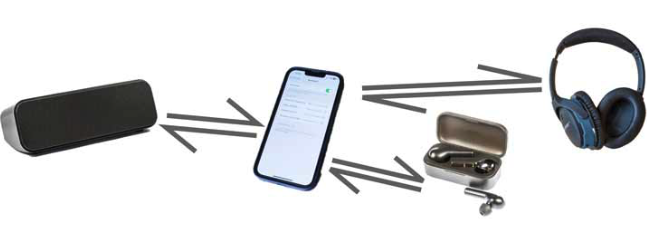
Do you struggle to get your Bluetooth devices to talk to each other? 🎧💻
Whether you are setting up brand-new wireless earbuds, a portable speaker, or a wireless mouse, the connection process doesn't need to be frustrating.
Wireless connectivity is supposed to make our lives easier, not leave us guessing.
In my video, I break down the exact step-by-step method to seamlessly pair any Bluetooth device to your smartphone or laptop in just a few clicks.
Here is the quick breakdown of how it works:
🔹 Power Up & Prep: Ensure your speaker, headphones, or earbuds are turned on and placed into "discovery mode" [00:24].
🔹 Scan for Devices: Head into your phone or laptop settings, navigate to the Bluetooth menu, and toggle it on [00:39].
🔹 Pair & Connect: Your device will scan the area, locate your gadget, and list its name. Just tap it to connect! (Pro-tip: Some devices may ask for a quick confirmation or pairing code to finalize the link).
The best part? Once you complete this setup the first time, your devices will remember each other and automatically pair in the future whenever they are turned on.
Check out the full, quick tutorial here to see exactly how to do it:
👉 youtu.be/Da59_9rlgu4
What's the one Bluetooth gadget you absolutely can't live without day-to-day? Let me know in the comments! 👇
#Bluetooth #TechTips #WirelessAudio #BluetoothEarbuds #ProductivityTech #electronicsnotes

4
647
Why do your wireless earbuds or smart sensors last for days or months on a tiny battery, while Bluetooth Classic drains power so quickly?
The secret lies in Bluetooth Low Energy (BLE). Introduced in Bluetooth v4 and heavily upgraded in v5, BLE is the technology behind many Internet of Things (IoT) devices, wearables, and modern consumer tech.
But how does it actually work?
Here are 4 core pillars that make BLE a powerhouse for low-power connectivity:
1. The 99.9% Inactivity Rule
Unlike Bluetooth Classic, which maintains a constant connection, BLE devices sleep for up to 99.9% of the time. They wake up in milliseconds, burst a quick packet of data, and go straight back to sleep. This extreme duty cycle is what saves massive amounts of battery.
2. Smart Role Play (Broadcasters to Centrals)
BLE introduces flexible communication topologies. A device can act as:
* Broadcaster / Beacon: Sends data one-way without accepting incoming messages (perfect for indoor positioning!).
* Observer: Listens to broadcasters without connecting.
* Peripheral: Periodically sends data (like a heart rate monitor).
* Central: Initiates the exchange and handles the data (like your smartphone).
3. Streamlined Frequency Hopping
Instead of the 79 channels used by Bluetooth Classic, BLE operates over 40 channels (with 2 MHz spacing) in the 2.4GHz ISM band.
* It dedicates 3 specific channels purely for Advertising (chosen carefully to avoid interference from local Wi-Fi networks!).
* The other 37 channels are used strictly for Data once a connection is locked in.
4. Modular Packet Structure
BLE uses Gaussian Frequency Shift Keying (GFSK) modulation. It wraps data tightly into efficient packets containing a Preamble (for sync), an Access Address (for security), a Protocol Data Unit (PDU - where your actual data lives), and a CRC for error checking.
From Bluetooth 4.2 onwards, the extended packet length jumped to 257 bytes, opening the door for faster, more robust data transfers.
With Bluetooth 5.x pushing boundaries with LE Coded PHY (for 4x the range) and LE 2M PHY (for 2x the speed), BLE has truly become the backbone of modern wireless engineering.
For the full breakdown see the link to my website in the comments.
#Wireless #IoT #BluetoothLowEnergy #EmbeddedSystems #ElectronicsEngineering #TechInnovation #BLE #electronicsnotes

2
8
30
1,674
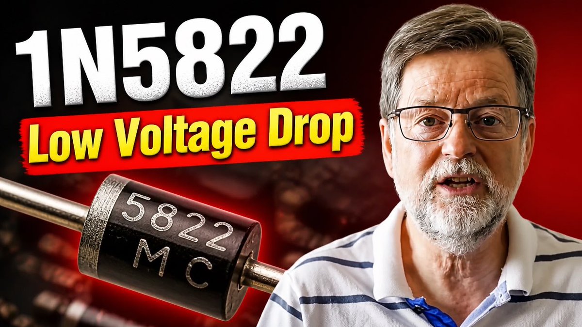
The 1N5822 Schottky Diode Guide
Are you looking for efficiency and to reduce power loss or improve switching efficiency in your next power electronics project?
In this video, I break down the 1N5822 Schottky diode and compare its performance directly to standard PN junction rectifiers like the 1N5408 series.
You’ll discover the benefits of its ultra-low 0.5V forward voltage drop and instantaneous switching speeds for DC-DC converters and reverse polarity protection.
I also cover critical Schottky pitfalls you must avoid, including its 40V reverse voltage limit and higher leakage current.
Understanding the 1N5822 Schottky Diode is essential for designing and building electronic circuits, and this video provides a great introduction to its uses and benefits.
Whether you're an electronics enthusiast, a student, or a professional engineer, this video will help you gain a deeper understanding of the 1N5822 Schottky Diode and its role in modern electronics.
Watch my video now: youtu.be/SurpzglsZ78
#1N5822 #Schottky #Schottkydiode #powersupplies #circuitdesign #HardwareDesign #electroniccomponents #electronicsnotes
8
47
1,607
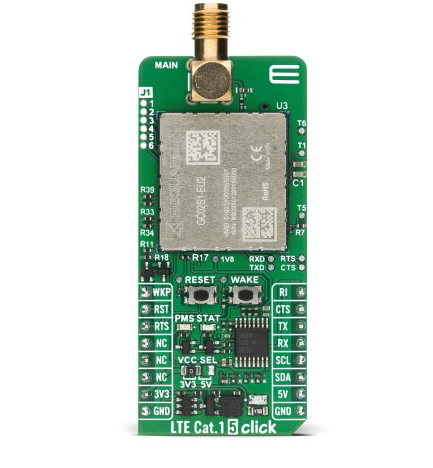
Big news for the IoT and M2M development community! MIKROE has just expanded its wireless connectivity portfolio with the launch of the LTE Cat.1 5 Click.
Tailored specifically for European applications, this new Click board™ brings reliable 4G LTE Cat 1 bis connectivity to projects where low power consumption and consistent data transmission are non-negotiable.
Why developers will love it:
✅ Based on the Sequans GC02S1-EU2 module: Features optimized Calliope 2 silicon for superior performance and energy efficiency.
✅ Ready for the Field: Perfect for utility meters, industrial sensors, asset trackers, security systems, and smart home devices.
✅ Seamless Integration: Like all boards in our 1975 strong Click board™ family, it features the ClickID function for automatic host identification and is fully compatible with the mikroBUS™ standard.
✅ Jumpstart Your Project: Access 875 working projects and code examples via EmbeddedWiki to move from proof-of-concept to prototype in record time.
Whether you're building a smart metering infrastructure or the next generation of wearable consumer tech, the LTE Cat.1 5 Click is designed to cut your development time and simplify your design process.
#IoT #EmbeddedSystems #4G #LTE #M2M #HardwareDevelopment #MIKROE #Innovation #IndustrialIoT #EuropeanTech #electronicsnotes
3
29
1,313
Power Dissipation in Zener Diode Regulators - Critical Details
In this video, I explain the steps that are needed to design a simple shunt regulator circuit using a Zener diode / voltage regulator diode.
I provide the basic details for this electronic circuit design for this voltage stabiliser circuit.
This shunt regulator circuit design can be used on its own, or it can be used as the basis of other transistor or FET regulator circuits.
In this video I outline the basic circuit details along with the calculations needed for the resistor, etc in this basic Zener diode regulator or voltage stabiliser circuit.
I take a look at the power dissipation levels for the components because it is necessary to ensure that none of the components is over-stressed.
Burn-out of the components is certainly not needed! In the video I state that the max current for the diode should be sufficient to accommodate variations in the load current.
For this example it was assumed that the load was unlikely to be completely removed - this can happen in some applications and the maximum Zener current should be the complete current with none passing to the load.
Having designed the basic circuit, I then go on to look at versions of the voltage regulator circuit that can enable higher current levels to be provided using emitter follower transistor circuits. I also detail some important points that need to be noted when designing these transistor circuits.
Check out my video now: youtu.be/Uv-mdGIcVLE
#zener #zenerdiode #circuitdesign #shuntregulator #voltageregulator #hardwaredesign #electronicsnotes

10
43
2,201
What was the first radio you owned?
For many of us, our introduction to electronics was through owning and experimenting with old radios.
My father built me a one transistor radio - basically a crystal set with a one transistor amplifier to power some old (uncomfortable) headphones. I must have been about five or six at the time.
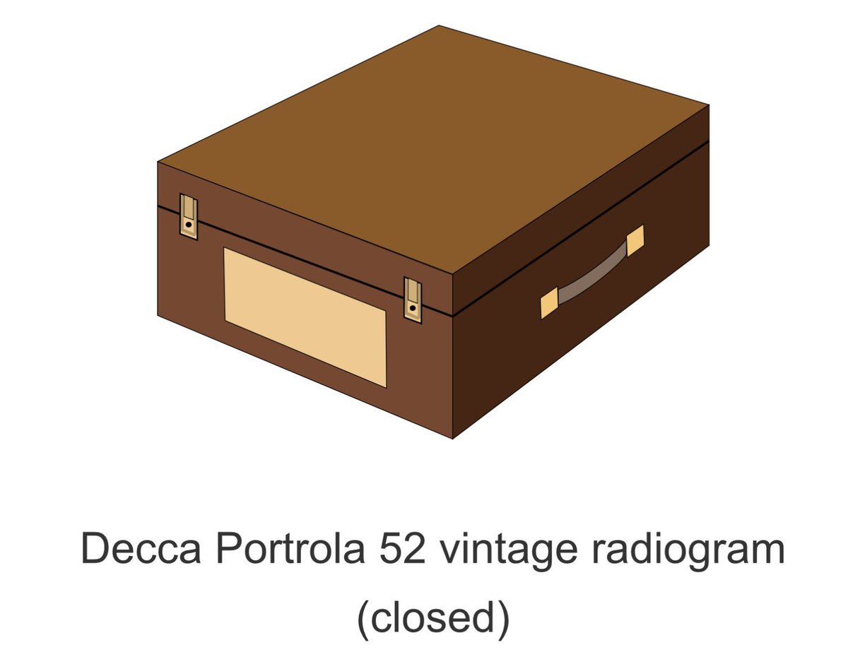
But the first real radio I owned was a Decca Portrola from around 1952 that a family friend wanted to pass on. I must have been about 13 at the time. It covered the long and medium wave bands and it had an old record deck.
I was fascinated! I could hear lots of distant broadcast stations, I could experiment with external home made speaker systems, and do so much more.
I then progressed into amateur radio and then a career in electronics.
Unfortunately I don’t have a photo of the Portrola, or of one I can reproduce here, so the diagram I created will have to do!
What’s your experience with getting into electronics / radio / communications. Was it via using an old radio or electronic gadget? Let’s share in the comments below.
#radio #amateurradio #hamradio #hamr #career #electronics #electronicsnotes
5
1
18
1,363
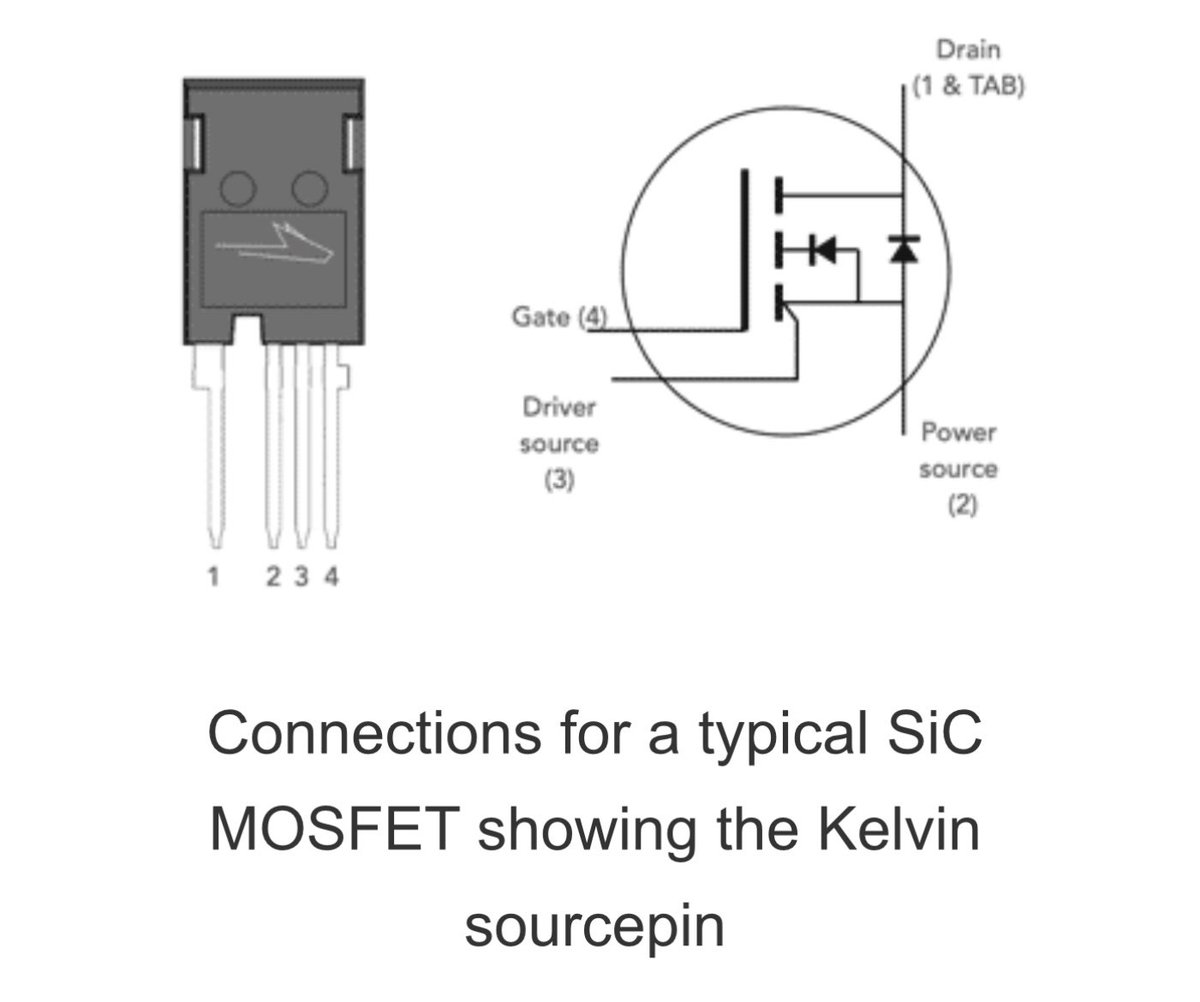
What Actually is the Kelvin Emitter Terminal used on IGBTs and SiC Power MOSFETs
Some IGBTs and SiC MOSFETs have an additional terminal known as a Kelvin emitter. It may be wondered what this is and how it should be used.
All will be explained . . . .
This extra terminal is connected to the emitter but routed from the die to the outside world as a separate terminal.
The Kelvin emitter is essentially a dedicated connection to the emitter terminal that is separate from the main power current path.
Its primary purpose is to provide a clean reference point for the gate drive circuit, minimizing the impact of voltage drops caused by the high switching currents flowing through the parasitic inductance and resistance of the main emitter connection.
The presence of a Kelvin emitter terminal provides a number of benefits:
Electronic components database
Accurate Gate Voltage Control: High and rapidly changing currents in the power emitter lead can induce voltage drops. If the gate drive circuit uses this point as its reference, these voltage fluctuations can interfere with the actual gate-emitter voltage seen by the IGBT die.
The Kelvin emitter terminal, carrying only the very small gate drive return current, avoids these voltage drops, ensuring a more accurate and stable VGE for precise switching control.
Improved Switching Performance: By providing a clean gate drive reference, the Kelvin emitter helps to achieve faster and cleaner switching transitions (both turn-on and turn-off). This reduces switching losses and allows for higher operating frequencies.
Enhanced Noise Immunity: The separation of the control and power paths improves the noise immunity of the gate drive circuit. Voltage transients on the power emitter are less likely to couple into the sensitive gate drive circuitry.
Reduced Oscillations: More precise gate voltage control, thanks to the Kelvin emitter, can help to dampen oscillations and ringing during switching transitions, leading to improved EMI (electromagnetic interference) performance.
Facilitates Optimized Gate Drive Design: With a more predictable and stable gate-emitter voltage, engineers can design more effective gate drive circuits, optimizing switching speed and minimizing losses without being overly affected by the power loop parasitics.
In essence, the Kelvin emitter is a technique, often implemented as an extra pin on the IGBT package (typically in a 4-pin configuration), to implement a four-terminal connection to the emitter.
So it’s really a very useful terminal where high current levels are being used.
#IGBT #insulatedgatebipolartransistor #SiC #MOSFET #electroniccomponents #kelvinterminal #powerswitching #powerelectronics #electronicsnotes
3
15
93
4,505
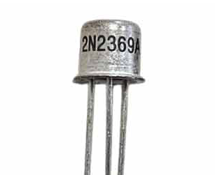
What was the 'Golden' secret behind the success of the 2N2369 switching transistor?
The 2N2369 has been a standard bipolar transistor when fast switching is required. But how did it come about and what is the secret behind its success?
The 2N2369 was developed during the mid-1960s, which was a period defined by the rapid expansion of early digital computing and high-speed pulse applications. The 2N2369 was designed specifically to minimize storage time - the delay that occurs when a transistor attempts to switch from a saturated "ON" state to its "OFF" state.
By optimizing the base-emitter and collector-base junctions for extremely low carrier lifetime, the engineering team created a device that could switch in nanoseconds, making it an essential component for the logic gates and pulse-shapers of that era.
The architecture of the 2N2369 relied on sophisticated planar manufacturing techniques, which were state-of-the-art at the time. This process allowed for highly precise control over the doping profiles of the silicon die, ensuring the device could maintain its rapid switching capabilities while remaining stable under varying electrical loads.
But what about its golden secret?
Find out all in my web page describing its development, performance and also giving distributor stock and pricing: electronics-notes.com/articl…
#2N2369A #transistor #datasheet #switchingtransistor #electroniccomponents #electronicsnotes
@oemsecrets
9
70
2,533
The OC71 Transistor: Myths, Legends & Performance
The OC71 was a legend of European transistor manufacturing. Launched in the 1950s it was widely used until silicon transistor technology took over in the 1960s.
Provided the circuits were designed to reduce the thermal runaway effect that affected all germanium transistors, it was very reliable. In fact many are still working perfectly well to this day.
They were used in everything from professional equipment to domestic radios and much more. They were everywhere.
In my video, I look at this transistor and one if the legends surrounding it, and I also explode some myths.
Which out my video now: youtu.be/BpxeOxuXjr0
#OC71 #vintageradio #transistor #Transistors #electroniccomponents #fuzzbox #electronicsnotes

1
1
26
1,152
Power Supply Smoothing: the key facts you need to know
Turning raw rectified AC power into the smooth DC that powers our sensitive electronics is a key technique in any analogue power supply.
The secret lies in a very important component: the Smoothing (or Reservoir) Capacitor.
Let’s take a look at why these components are able to provide essential smoothing in both linear and switch-mode power supplies.
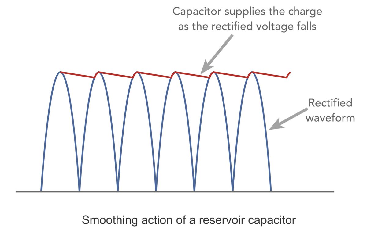
If you’ve ever seen a "raw" rectified waveform, you know it’s a series of peaks and valleys - basically useless for either an analogue or digital circuit.
Here are the key takeaways from the full article:
✅ The "Gap Filler" Effect: A smoothing capacitor acts like a temporary battery. It charges up during the voltage peaks and discharges its stored energy when the rectifier voltage drops. This "fills in the dips," resulting in a much steadier DC output.
✅ The Ripple Reality: Total stability is a myth. There will always be some "ripple voltage." The trick to minimizing it? A larger capacitor value and a higher ripple frequency (which is why full-wave rectification is always preferred over half-wave). But beware as the capacitor gets larger, so the charge spikes where the capacitor charges up become shorter and the current higher.
✅ The Critical Calculation:
Choosing the right value isn't guesswork. The time constant (R C) must be significantly longer than the time between peaks. For a full-wave rectifier:
V_(ripple) = I_(load) / (2fC)
✅ The Hidden Danger: Ripple Current:
This is where many designs fail. The capacitor doesn’t just sit there; it handles intense bursts of current during the charging phase. If you exceed the "Ripple Current Rating," your capacitor will heat up, its lifespan will plummet, and it could even fail catastrophically.
✅ Why Electrolytics Rule:
Aluminum electrolytic capacitors are the standard here. They offer the high capacitance needed to handle large currents at a cost-effective price point.
Whether you are designing a high-end audio amp or a simple DIY power supply, understanding the relationship between load, frequency, and capacitance is vital for a stable, long-lasting circuit.
Want to see the calculations and the circuit diagrams behind this?
Check out the link in the comments for more information.
#ElectronicsEngineering #PowerSupply #CircuitDesign #ElectricalEngineering #electronicsnotes #LearningElectronics
1
11
88
3,619
Was the Transistor Nearly Named the Iotatron?
Imagine if your electronic gadgets ran on an Iotatron instead of a transistor...
We use them by the millions every single day, but the birth of the transistor actually started with a massive failure at Bell Labs.
Before it became the backbone of modern technology, it was just a makeshift piece of gold-plated perspex wedge held onto some germanium by a spring.
And the name? It took a lot of head-scratching to avoid some truly awful, clunky titles.
👉 Watch the video to see the bizarre names that were almost chosen, and check out the full long-form video on the channel to find out the secret connection to a famous science fiction writer!
Check out my video now: youtube.com/shorts/zolY5j91s…
#transistorhistory #iotatron #techhistory #transistor #electroniccomponents #electronicsnotes
3
17
1,034
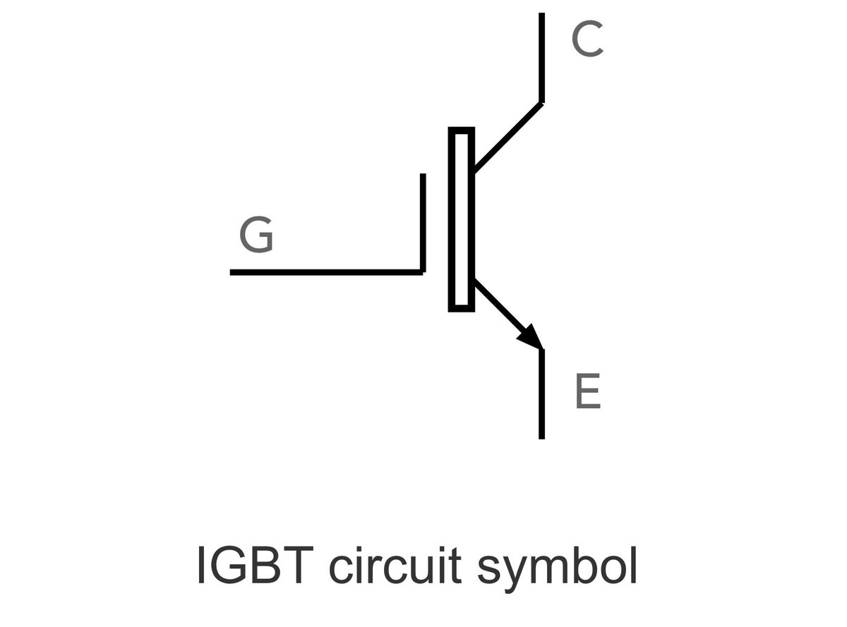
What is an IGBT & why is it an Electronics Powerhouse
Have you ever wondered how we efficiently manage high power in everything from electric vehicles to renewable energy systems? The IGBT (Insulated Gate Bipolar Transistor) is one solution.
As electronics engineers, we often face a trade-off between the fast switching of MOSFETs and the high-voltage capability of BJTs.
The IGBT was designed to solve this exact dilemma by merging the best features of both technologies into a single semiconductor device.
Key Highlights of the IGBT:
🔹 Hybrid Performance: It features the high input impedance and fast switching of a MOSFET, combined with the low saturation voltage and high current handling of a Bipolar Transistor.
🔹 Voltage Controlled: Like a MOSFET, it’s easy to drive—requiring only a small voltage at the gate to switch high current levels.
🔹 Efficiency: With a very low ON-resistance, it minimizes power dissipation, making it ideal for high-power applications.
Where do we see them in action?
• Motor Control & Traction: Powering the drive systems in EVs and trains.
• Renewable Energy: Converting DC power from solar panels into AC for the grid.
• SMPS & Inverters: Providing the heart of efficient power supplies and industrial inverters.
• Inductive Loads: Handling the heavy lifting in industrial machinery.
While they may not be as fast as pure MOSFETs at lower power, their ability to handle thousands of volts and hundreds of amps makes them indispensable in the push for a more electrified and sustainable future.
Check out the full breakdown of how they work, their physical structure, and the difference between PT and NPT types - use the link in the comments.
#PowerElectronics #Engineering #Semiconductors #IGBT #ElectricalEngineering #RenewableEnergy #EVTechnology #ElectronicsNotes
3
13
68
1,991