
Jun 12
Missing a tiny standoff mid-build? We’ve all been there. 🛠
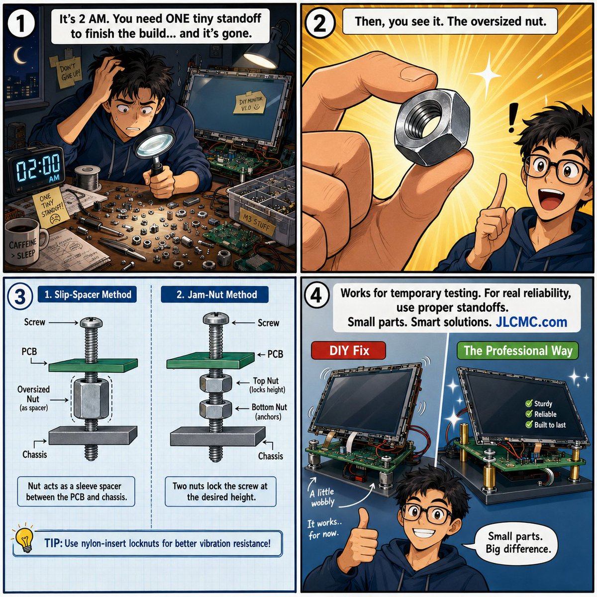
When you're assembling a DIY monitor, an electronics enclosure, or a quick prototype, running out of the exact spacer you need can stall the whole project.
Here are two quick mechanical hacks to keep your workflow moving using standard nuts:
1️⃣ The Slip-On Collar: Pass a long machine screw through your PCB, slide a larger-diameter nut over it as a temporary metal spacer, and secure it at the chassis.
2️⃣ The Jam Nut Height Adjuster: Thread a nut onto a long bolt, adjust it to your desired height, place the board on top, and lock it in place with a second nut.
⚠ The Catch?
While these workarounds are great for quick layout checks and light-duty prototyping, they aren't built for the long haul. Vibration, thermal expansion, and production loads require precision.
Don't let a temporary fix become a permanent risk. For long-term reliability, repeatable spacing, and professional-grade fastening, switch to properly rated hardware.
From quick proof-of-concepts to production-ready builds, JLCMC has your back with a massive inventory of mechanical components:
🔩 Screws & Bolts
⚙ Precision Nuts
⭕ Washers & Shims
📏 Threaded Standoffs (Brass, Nylon, Stainless Steel)
🧩 Fastener Accessories
👉 Streamline your assembly at jlcmc.com?from=IAVNQIBKPEV
#JLCMC #Fasteners #Standoffs #MechanicalDesign #Mechatronics #EngineeringTips #PrototypeAssembly #DIYElectronics #HardwareHack
55

Tired of plugging/unplugging USB drives for oscilloscope data?
Save CSV waveforms, PNG screenshots & more directly to your PC via SMB — no hassle, faster workflow, and bypasses corporate USB restrictions!
👉Step-by-step guide here: bit.ly/3Sd96Nz
#Siglent #Oscilloscope #EngineeringTips

3
58

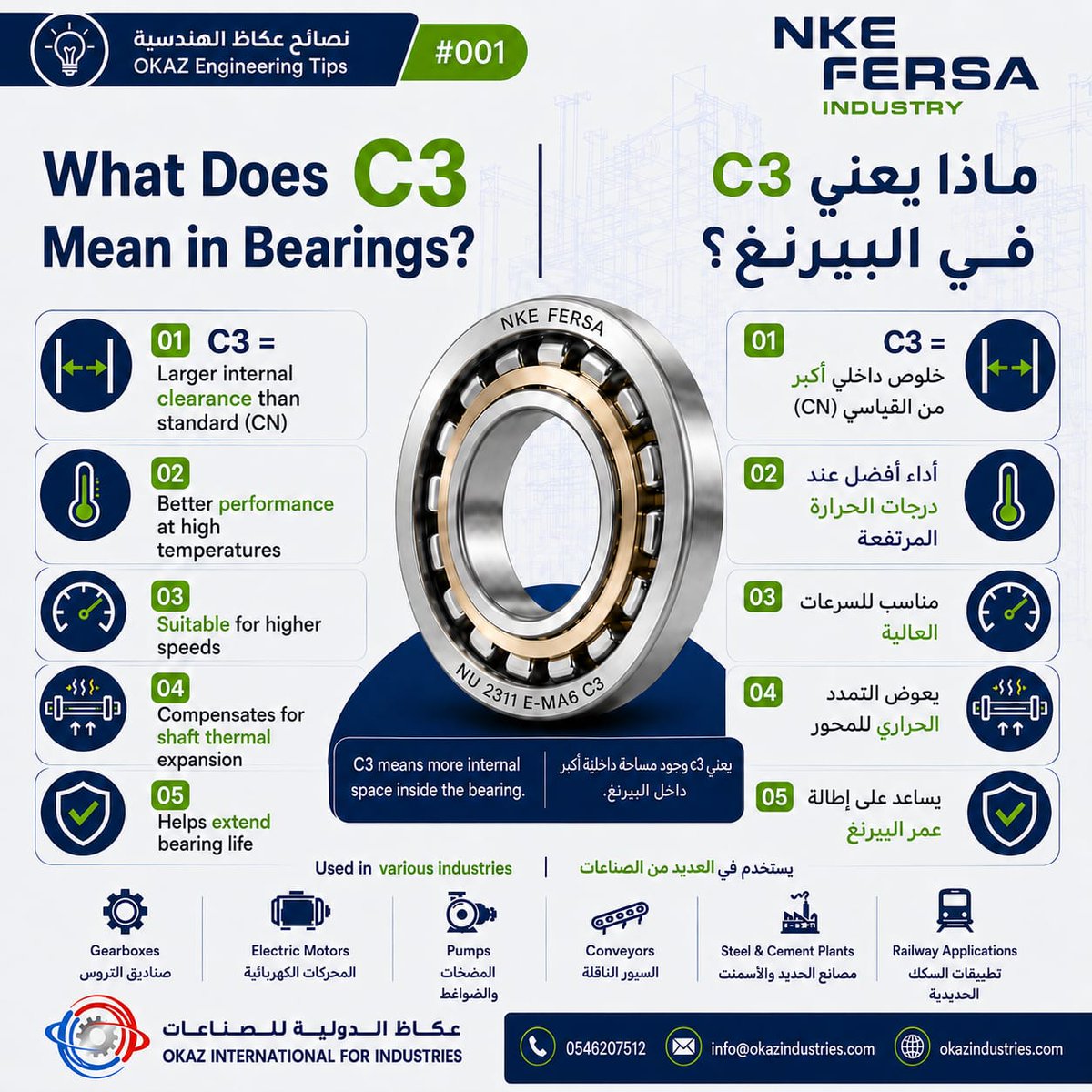
🔧 OKAZ Engineering Tips #001
What does C3 mean in bearings?
C3 means greater internal clearance than standard, making it ideal for higher temperatures and speeds while helping extend bearing life.
#OKAZIndustries #EngineeringTips #Bearings #IndustrialSolutions #MaintenanceTips
3

Jun 8
Don't guess—use the right tool for the job. 🛠️ Here is your ultimate guide to the most common types of washers and when to use each one.
#AlboHardware #EngineeringTips #DIYProjects #HardwareGuide #WorkshopEssential #MechanicTips #Construction
2

The Transistor as a Switch: Back to Basics
We often talk about transistors as amplifiers—the building blocks of audio gear and signal processing. But arguably the most common use of the bipolar transistor in modern embedded design is much simpler: The Electronic Switch.
Whether you’re driving a relay, an LED, or a small motor from a microcontroller pin, understanding how to drive a transistor into saturation is a fundamental skill for any hardware engineer.
I’ve just updated my guide on using the transistor as a switch, covering the essential principles of getting it right.
Key concepts for a reliable design:
✅ Saturation vs. Active Region: How to ensure your transistor is fully "ON" to minimize heat and maximize power efficiency.
✅ The Importance of Base Resistors: Why you should never connect a microcontroller pin directly to the base of a BJT.
✅ Choosing the Right Driver: Understanding gain and collector current limits to keep your circuit robust.
If you’re working on an Arduino, Raspberry Pi, or any custom PCB project, this is the "bread and butter" of your design workflow. Getting the switching logic right is the difference between a reliable prototype and a burned-out component.
Read the full breakdown on my Electronics Notes website: 👉 electronics-notes.com/articl…
Quick poll: When you’re driving a load from a microcontroller, are you reaching for a BJT, a MOSFET, or a dedicated driver IC? Let me know your go-to components in the comments! 👇
#ElectronicsEngineering #PCBDesign #EmbeddedSystems #CircuitDesign #Transistors #HardwareDevelopment #EngineeringTips #MakerSpace
1
11
62
2,042
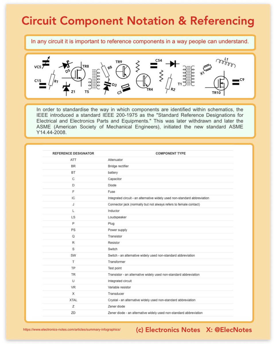
Circuit Schematic Text Notations
Have you ever at a circuit schematic and wondered what all those tiny letter-number combinations actually mean?
While the graphical symbols show us what a component is, the text notations (or reference designators) tell us exactly which one it is and how to find it in a Bill of Materials (BOM). They are also standardised.
Standardizing these notations isn’t just about being tidy—it’s about clear communication between engineers, PCB designers, and assembly teams worldwide.
Based on the latest infographic from Electronics Notes, here is a quick guide to the shorthand that keeps our industry moving:
1. The Reference Designator System 🏷️
Most notations follow a simple formula: Letter(s) Number. The letter identifies the component type, and the number distinguishes it from others of the same type (e.g., R1, R2, R3).
2. Common Standards (IEEE & Beyond)
While standards like IEEE 200-1975 laid the groundwork, some abbreviations have become universal shorthand in the lab:
• R = Resistor
• C = Capacitor
• L = Inductor (Coil/Choke)
• D = Diode (including LEDs)
• Q or TR = Transistor
• U or IC = Integrated Circuit
• SW or S = Switch
• J = Jack/Connector (Female)
• P = Plug/Connector (Male)
• T = Transformer
• TP = Test Point
3. Layout Conventions 📐
A well-notated schematic is also a well-organized one. Beyond just the labels, professional schematics follow "unwritten" rules for clarity:
• Signal Flow: Generally flows from left to right.
• Voltage Rails: Higher voltages are typically placed at the top of the section.
• Ground/Earth: Always placed at the bottom.
• Tidiness: Avoid "spaghetti" wiring—keeping labels near their symbols prevents errors during the PCB layout phase.
Why it matters:
Whether you are hand-soldering a prototype or managing a massive manufacturing run, accurate notation prevents "wrong part" errors. If your schematic says R14 and your BOM says 10kΩ, everyone knows exactly what to do. Without those notations, it’s just a guessing game.
Link in the comments if you want more information.
#ElectronicsEngineering #PCBDesign #ElectricalEngineering #CircuitDesign #Schematics #EngineeringTips #STEM #electronicsnotes
2
3
61
2,095
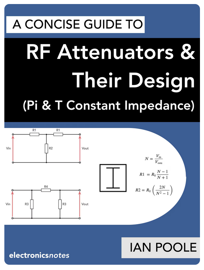
Why do we need RF attenuators? It’s not just about turning down the volume!
Whether you’re preventing receiver overload, improving impedance matching, or isolating stages in a high-frequency circuit, a well-designed attenuator is an essential tool in every RF engineer’s arsenal.
(1/4)
#RFEngineering #Electronics #WirelessTech #CircuitDesign #RadioCommunication #EngineeringTips #RFdesign
2
6
59
2,022
Why COB LEDs are Revolutionizing the Lighting Industry
Are you still using traditional SMD matrices for your lighting designs? It might be time to switch to Chip-on-Board (COB) technology.
Unlike standard LEDs, COB technology mounts multiple bare LED chips directly onto a substrate to form a single module.
This "small but mighty" approach is changing the game for industrial, domestic, and professional lighting.
Based on the information from the Electronics Notes website, here is why COB technology is becoming the "only viable option" for modern RF and electronic designs:
✅ High Packing Density: COB can contain up to 50 times more LED elements in the same area compared to leaded or SMD designs. More light, less space.
✅ Superior Uniformity: Forget the "pixelated" look of discrete LEDs. COB provides an incredibly even light distribution—a huge advantage for photography and architectural down-lighting.
✅ Enhanced Reliability: By mounting chips directly to the substrate, we eliminate the need for individual soldering of SMD packages. Fewer electrical joints = lower failure rates.
✅ Thermal Efficiency: The direct-to-substrate bonding allows for much more effective heat removal, ensuring the longevity of the module.
✅ Design Simplicity: Why deal with complex wiring for dozens of LEDs? A COB module typically requires only two connections, simplifying your PCB layout significantly.
Where is this being used?
From high-intensity torches and domestic down-lighters to professional photography backlighting, the applications are growing as performance improves and costs continue to fall.
Pro-Tip for Designers: When implementing COB LEDs, remember that thermal management is key! Whether using passive heat sinks or active cooling, keeping these high-density modules cool is the secret to maintaining their impressive luminous flux.
Do you use COB LED technology and how have you found it?
For more information check out the links in the comments.
#ElectronicsEngineering #LEDTechnology #LightingDesign #COBLED #Innovation #EngineeringTips #electronicsnotes #electroniccomponents

3
2
18
1,134

Mini USB Connector Assembly Tips for Stronger Joints
#SolderingTips #ElectronicsManufacturing #PCBA #HardwareDesign #EngineeringTips
1
13
2,305
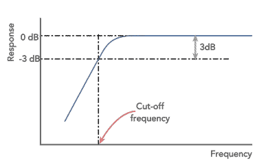
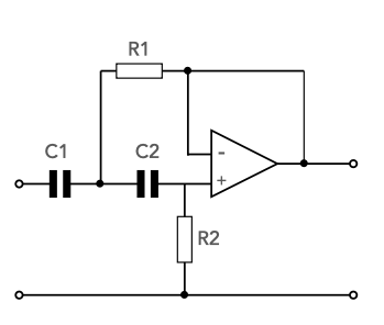
High Pass Active Filter Design: Simplified with Op-Amps!
Looking to eliminate low-frequency hum or noise from your analogue circuits? Using an Operational Amplifier (Op-Amp) is one of the most effective ways to build a high-performance high-pass filter without the need for bulky inductors.
I’ve put together a comprehensive guide on designing Active High Pass Filters, focusing on the popular Butterworth response—known for its flat passband and straightforward design equations.
Key Highlights:
✅ Why Active? Unlike passive filters, op-amp circuits provide gain (if needed) and prevent signal loading due to their high input impedance.
✅ Single-Pole vs. Two-Pole: Learn how a single capacitor/resistor pair gives you 6dB/octave, or step up to a Sallen-Key configuration for a sharper 12dB/octave roll-off.
✅ Design Shortcuts: For a 2-pole Butterworth response with unity gain, the math is surprisingly simple!
* Set R_1 = R_2
* Set C_1 = 2 . C_2
* Calculate your cut-off frequency: f = √2 / (4 π R C2)
Pro-Tips for Your Build:
📍 Resistor Selection: Aim for 10kΩ to 100kΩ to keep output impedance stable.
📍 Capacitor Choice: Avoid electrolytic capacitors! Stick with Ceramic or Plastic Film for better tolerance and stability.
📍 Cascading: Need a steeper slope? You can cascade these stages to achieve 24dB, 36dB, or higher roll-off rates.
Dive into the full circuit diagrams and component selection guide here:
🔗 electronics-notes.com/articl…
#ElectronicsEngineering #CircuitDesign #OpAmps #AnalogDesign #ElectricalEngineering #EngineeringTips #ElectronicsNotes
5
57
1,636
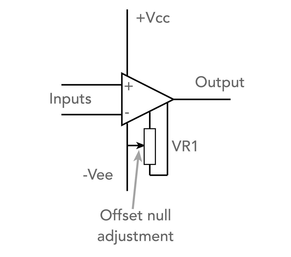
Op-Amp Offset Null: what it is and where to use it!
If you’ve ever shorted the inputs of an operational amplifier and still seen a voltage at the output, you’ve encountered Input Offset Voltage. It’s not just seen when you short the inputs - it’s very important when amplifying low level signals like those you see from sensors.
In a perfect world, an op-amp is a balanced differential amplifier. In the real world, tiny mismatches in the internal transistor pairs, collector resistors, or current gains (β) during manufacturing create an inherent imbalance.
While this might not matter in AC-coupled circuits, for DC amplifiers, instrumentation, and sensor applications, it’s a critical challenge. Any small offset at the input is amplified by the gain of the circuit, leading to significant errors at the output.
The Solution: The Offset Null
Many op-amp ICs (like the classic 741) feature specific "Offset Null" pins. Here is how it works:
✅ The Purpose: The offset null capability is used to remove inherent DC offsets by balancing the internal circuitry.
✅ The Fix: Usually, all it takes is a single external potentiometer (typically 10kΩ to 100kΩ). The wiper is connected to the negative supply (or 0V, depending on the datasheet), allowing you to manually "null" the output to zero.
✅ The Drift Factor: Remember that offsets can drift with temperature. For high-precision applications, you might need temperature compensation or digital feedback loops to keep that offset at bay.
Whether you are designing precision instrumentation or just troubleshooting a DC-coupled circuit, understanding the offset null is key to achieving high accuracy.
If you need to find out more, check the link to my web page in the comments.
#ElectronicsEngineering #CircuitDesign #OpAmps #AnalogDesign #electronicsnotes #EngineeringTips
1
1
52
2,105
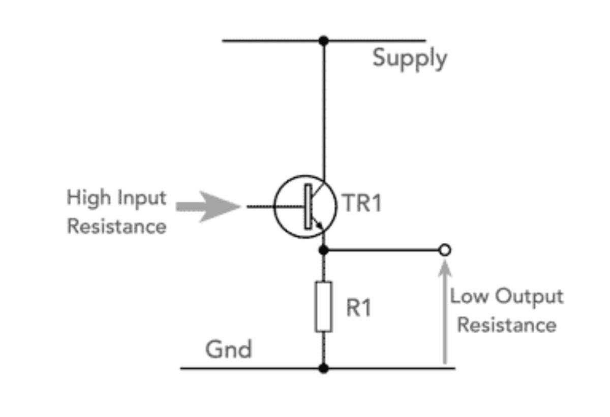
The "Useful Companion" of Analogue Design: Why the Emitter Follower is an Essential Buffer Circuit
Want to connect a high-impedance source to a low-impedance load without the signal collapsing?
Meet the Emitter Follower (also known as the Common Collector configuration).
While it might not give you a voltage boost, its real benefits lie in impedance transformation - making it an essential building block in everything from audio amplifiers to power supplies and very much more.
Key Features You Need to Know:
🔹 High Input Impedance: It doesn't "load down" the previous stage, ensuring signal integrity.
🔹 Low Output Impedance: It can drive heavy loads or low-resistance stages with ease.
🔹 Unity Voltage Gain: The output voltage "follows" the input (minus a small 0.7V B-E drop), giving it its famous name.
🔹 Current Gain: While voltage stays the same, it provides significant current gain, acting as a powerful buffer.
Where do we use it?
It’s the ultimate "matching" circuit. Whether you’re designing an output stage for an amplifier or stabilizing a voltage regulator, the Emitter Follower ensures your signal gets where it needs to go without losing its strength.
Pro-Tip: Remember that because the collector is at signal ground, the circuit is often referred to as the "Common Collector." It’s all about providing that stable, low-impedance path!
Are you using Emitter Followers in your latest project? Let’s talk analogue design in the comments! 👇
Much more information in the link in the comments.
#ElectronicsEngineering #CircuitDesign #AnalogElectronics #EngineeringTips #transistor #electronicsnotes #HardwareDesign
2
12
113
4,589
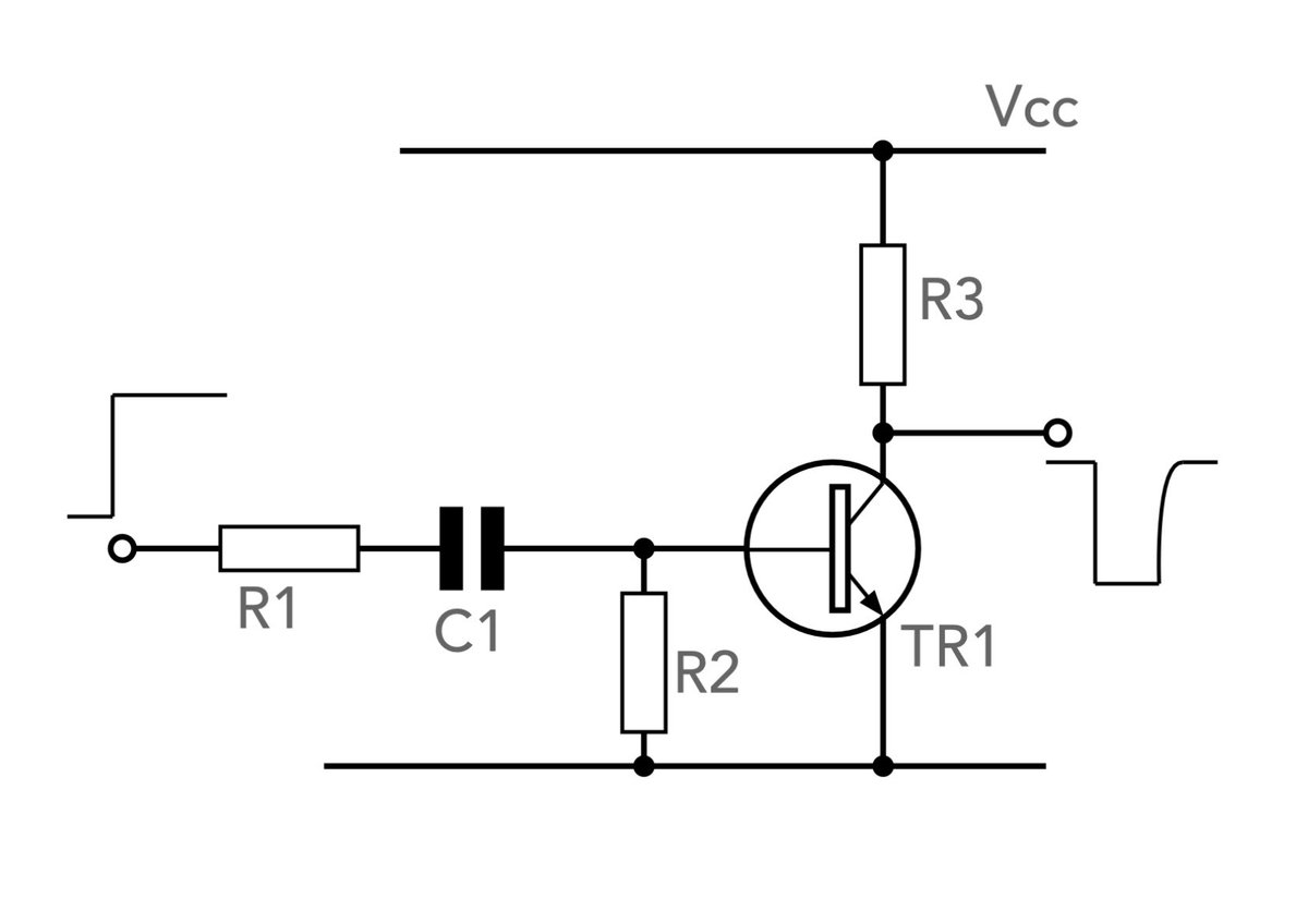
Back to Basics: Creating Short Pulses with Simple Transistor Circuits
Sometimes the best solution to a design challenge isn't a complex IC or a microcontroller—it’s a handful of discrete components and a fundamental understanding of circuit behaviour.
If you’ve ever needed to trigger a logic circuit or generate a timing pulse from the edge of a square wave, a Transistor Pulse Generator is a tool every engineer should have in their back pocket.
In my latest summary, I explore how to design these using simple Bipolar Junction Transistors (BJTs). It’s also similarly possible to use FETs, but here’s the bipolar version.
How it works:
The key combination is a CR (Capacitor-Resistor) network acting as a differentiator. When a rising edge hits the network, the capacitor passes a brief "spike" as it charges.
By pairing this with a transistor, we can:
✅ Clean up the pulse into a sharp, usable square wave.
✅ Remove unwanted negative-going spikes.
✅ Invert or maintain the polarity of the input signal.
Two configurations to consider:
1. The One-Transistor Design: Ideal for simplicity, providing a negative-going pulse from a positive-going input.
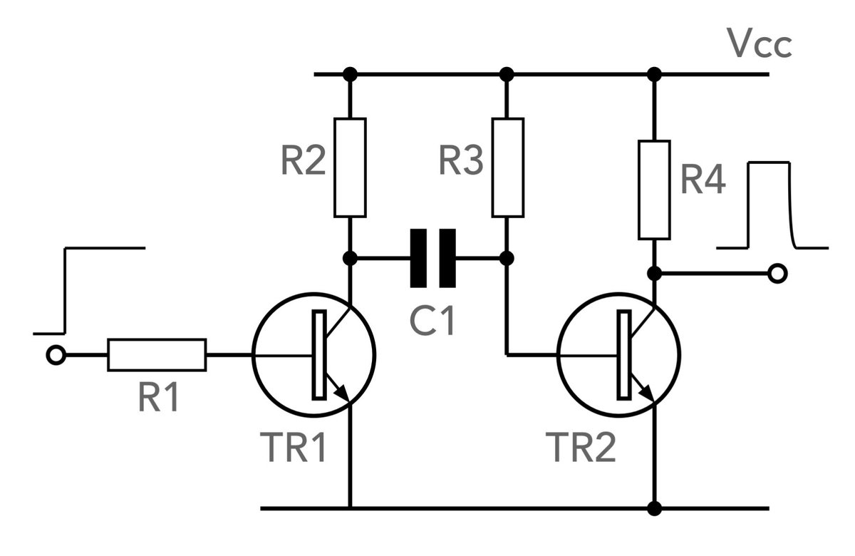
2. The Two-Transistor Non-Inverting Design: Uses two capacitively coupled NPN switches to create a positive pulse from a rising edge—a common requirement for TTL logic.
A Quick Tip for the Workbench:
When designing the two-transistor version, be mindful of your rail voltage! If it exceeds ~7V, the negative voltage spike at the base-emitter junction could cause a breakdown. Keeping it around 5V (standard logic level) is the "sweet spot" for reliability.
Discrete designs like these remind us that even in an age of SOCs, there is still immense value in straightforward, cost-effective analog building blocks.
Want more information? Check the link in the comments.
#ElectronicsEngineering #CircuitDesign #HardwareDesign #AnalogElectronics #ElectricalEngineering #EngineeringTips #electronicsnotes
2
20
200
9,998

Apr 30
What is CNC coolant used for? Think it’s just for cleaning? 3 key functions you should know.💡
Get a quick breakdown in this video.
Follow JLCCNC for more CNC machining tips and insights.
#jlccnc #cnc #cncmachining #manufacturing #engineeringtips #prototyping #toollife #cncparts #cnccoolant #coolantsystem #cncknowledge #cncfaq
2
506
Searching for the "perfect" op-amp?
In circuit design, the "ideal" op-amp (infinite gain, zero noise, infinite bandwidth) doesn't exist. Instead, successful engineering is about finding the right balance between performance, availability, and cost.
Whether you're building a precision integrator or a simple buffer, here’s a quick guide on how to navigate your selection, inspired by the deep dive over at Electronics-Notes:
🔹 Assess Your Primary Need:
* High Input Impedance: If you’re working with sensors or integrators where charge leakage is a concern, look for **FET-input** op-amps.
* Low Noise: Crucial for the initial stages of a signal chain. Remember, noise added at the start gets amplified by every subsequent stage.
* Low Power: Essential for battery-operated devices. Look for "micropower" versions that trade off speed for longevity.
* Rail-to-Rail: If your supply voltage is low (e.g., 3.3V), ensure your op-amp can handle swings close to the supply rails.
🔹 Think Beyond the Specs:
* Packaging: Do you need breadboard-friendly DIP-8 or space-saving SMT? Don't forget that dual or quad packages can save board space, but they often lack offset null pins.
* Availability & Sourcing: For commercial projects, "jellybean" parts (like the classic LM358 or UA741) are easier to source and often have multiple manufacturers, reducing supply chain risks.
* Lead Times: Sometimes the "best" chip is the one you can actually get delivered by your distributor today!
Pro Tip: Don't over-specify. Increasing performance requirements unnecessarily can inflate costs and restrict your supplier options.
For more information check out the link in the comments.
#ElectronicsEngineering #CircuitDesign #HardwareDesign #OpAmp #EngineeringTips #ElectronicsNotes

4
12
69
3,136
Apr 27
What’s the difference between CNC Turning and CNC Milling?
Get a quick breakdown in this video.
Follow JLCCNC for more CNC machining tips and insights.
#jlccnc #cnc #cncmachining #cncturning #cncmilling #manufacturing #engineeringtips #prototyping #cncknowledge #cncfaq
3
418
Apr 26
What is CNC coolant used for? Think it’s just for cleaning? 3 key functions you should know.💡
Get a quick breakdown in this video.
Follow JLCCNC for more CNC machining tips and insights.
#jlccnc #cnc #cncmachining #manufacturing #engineeringtips #prototyping #toollife #cncparts #cnccoolant #coolantsystem #cncknowledge #cncfaq
3
547
Small, Mighty, and Unforgiving: The Tantalum Capacitor
When space is at a premium but performance is non-negotiable, the Tantalum Capacitor is often a great option.
Unlike their larger aluminium electrolytic cousins, tantalum capacitors are the "powerhouses of density." They offer one of the highest levels of capacitance per unit volume of any capacitor type, making them essential for modern, compact electronics. What's more they're available in both leaded and SMD formats.
But what makes them truly stand out in a design? Based on our deep dive at Electronics Notes, here is what every engineer needs to know:
The Tantalum Advantage:
✅ Volumetric Efficiency: Incredible capacitance-to-size ratio.
✅ Stability: Excellent temperature stability and flat frequency response compared to aluminum types.
✅ No "Dry-Out": Unlike liquid electrolytes, tantalum capacitors have a long shelf-life and don't degrade over time through evaporation.
✅ High Reliability: Ideal for mission-critical applications in medical, aerospace, and high-end consumer tech.
The "Catch" (What to Watch Out For):
Every component has its quirks, and for tantalum, it's all about the voltage.
* Polarity is Critical: Reverse the voltage even slightly, and you risk catastrophic failure. 💥
* Voltage Derating: A gold standard for engineers is to derate these by at least 50% of their rated voltage to handle current surges safely.
Whether you are designing the next generation of wearables or high-reliability industrial sensors, understanding the chemistry and construction of these small but mighty components is key.
🔗 Want to master the nuances of tantalum construction, MnO2 vs. Polymer types, and failure modes? Read the full guide here: electronics-notes.com/articl…
#ElectronicsEngineering #PCBDesign #Components #Tantalum #HardwareDesign #EngineeringTips #Capacitors #ElectronicsNotes #electroniccomponents

4
11
61
3,752
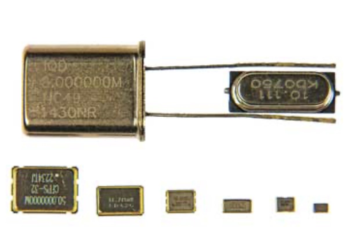
Don’t Let Your Design Drift: How to Specify a Quartz Crystal
If you’ve ever had an oscillator fail to start or drift off frequency, you know that specifying a quartz crystal involves much more than just picking a frequency.
Based on the expert guide from Electronics Notes, here is the essential checklist for specifying a crystal resonator that ensures reliability and precision.
1. Nominal Frequency & Mode
It’s standard to specify frequency to six decimal places (e.g., 25.000000 MHz). But don’t forget the Mode:
• Fundamental: Typical for frequencies up to ~30 MHz.
• Overtone: Used for higher frequencies (3rd, 5th, or 7th overtone).
2. Resonance Mode & Load Capacitance (CL)
This is the most common area for errors.
• Series vs. Parallel: Most modern ICs use parallel resonance.
• CL is key: This is the capacitance the crystal "sees" from your circuit. If your crystal is rated for 10pF but your circuit provides 20pF, your frequency will shift (pull).
3. Frequency Tolerance & Stability
• Tolerance: The allowable deviation at 25°C (usually ±10 to ±50 ppm).
• Stability: How much the frequency drifts over the Operating Temperature Range (e.g., -40°C to 85°C).
4. ESR (Equivalent Series Resistance)
As packages get smaller, ESR tends to go up. If ESR is too high, your oscillator might not start. Always check that your IC’s gain can overcome the crystal's maximum ESR.
5. Drive Level (DL)
This is the power dissipated in the crystal (measured in µW). Over-driving a tiny SMD crystal can cause "frequency jumps" or even physical damage to the quartz blank.
6. Ageing
Crystals change frequency over time, usually following a logarithmic curve. A typical spec is ±3 ppm for the first year.
The Specification Checklist:
When ordering or searching a datasheet, make sure you have these 9 points covered:
✅ Frequency (MHz)
✅ Mode (Fundamental/Overtone)
✅ Load Capacitance (CL in pF)
✅ Frequency Tolerance (ppm @ 25°C)
✅ Frequency Stability (ppm over Temp)
✅ Operating Temp Range (°C)
✅ Max ESR (Ohms)
✅ Max Drive Level (µW)
✅ Package Style (e.g., SMD 3225)
Getting these right at the start prevents "hidden" bugs that only show up in mass production or extreme temperatures!
More details in the link in the comments.
#ElectronicsEngineering #CircuitDesign #HardwareDesign #electroniccomponents #PCBDesign #EngineeringTips #electronicsnotes
2
2
37
1,933

Apr 19
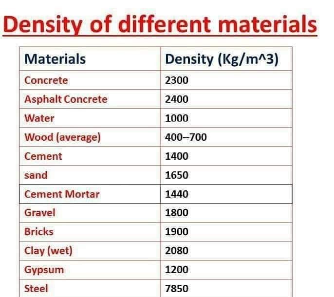
📋⚙️ Knowing material densities is essential for accurate load calculations in every structure.
.
Hey @grok, why is steel density 7850 kg/m³ so important in structural engineering calculations? 🤔🏗️
.
#MaterialDensity #CivilEngineering #StructuralEngineering #EngineeringTips
2
2
55