
At High Frequencies, a Capacitor is No Longer Just a Capacitor.
If you work in RF or high-speed digital circuit design, you quickly learn a harsh truth: selecting a capacitor is rarely about the capacitance value on the label. Instead, it’s about managing the component's parasitic behaviour.
In high-frequency environments, a real-world capacitor transforms into a complex RLC series circuit. If you don't account for this, your circuit will suffer from unexpected heat, power loss, or even complete signal inversion.
Here is a quick engineering guide to mastering high-frequency capacitor selection:
1. The ESR and ESL Trap
* ESR (Equivalent Series Resistance): Generates unwanted heat and power / signal loss.
* ESL (Equivalent Series Inductance): Created by physical leads and internal structures. At ultra-high frequencies, ESL dominates, causing the capacitor to behave like an inductor.
* The Rule: Choose components that stay firmly in their "capacitive region" across your target operating frequency.
2. Dielectric Matters: The RF Hierarchy
Not all ceramic capacitors are built equal. Your choice of dielectric dictates stability:
* C0G / NP0: Ultra-stable over temperature/voltage with low loss (High Q). * Use for: Tuning circuits, filters, and precision timing.
* X7R: Decently stable. *Use for:* General-purpose decoupling.
* Y5V / Z5U: High loss and massive capacitance drift with temperature. Rule of thumb: Avoid these completely in RF designs.
3. Package Geometry: Smaller is Better
In RF, physical size is a technical specification. Smaller surface-mount (SMD) packages like 0402 or 0201 inherently have less lead inductance than larger 1206 packages. Minimizing size pushes your Self-Resonant Frequency (SRF) higher, ensuring the component doesn't accidentally become inductive.
4. The Multi-Decoupling Strategy
No single capacitor can clean up a wide frequency range. Successful designs often run a hierarchy in parallel:
* Bulk low-frequency ripple ➡️ Tantalum or Electrolytic
* Mid-range noise ➡️ 0.1µF X7R
* High-frequency shunt ➡️ Small 10nF or 100pF C0G/NP0 placed as close to the IC pin as possible.
(Bonus tip: Watch out for anti-resonance humps where parallel caps interact!)
Bench Tip: Uncertain about a component’s real-world SRF? Pop the capacitor across a test fixture on a Vector Network Analyzer (VNA) and measure the S21 parameter. The bottom of the resulting "V" curve marks your exact self-resonance point.
What are your go-to layout tricks for minimizing loop inductance in high-speed designs? Let’s discuss in the comments! 👇
Read the full guide in the link in the comments.
#HardwareEngineering #RFDesign #PCBDesign #CircuitDesign #ElectronicsEngineering #HighSpeedDigital #electroniccomponents #electronicsnotes

5
24
194
9,467

22 Oct 2025
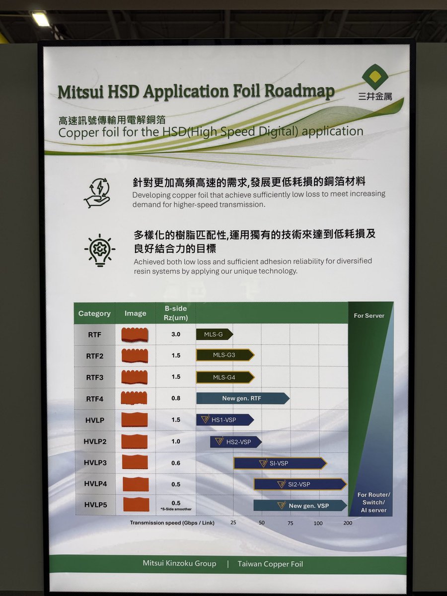
Mitsui Metals showcases its HSD (High-Speed Digital) Copper Foil Roadmap, revealing how smoother, low-loss copper foils are evolving to meet next-generation transmission needs.
From RTF to HVLP foils, surface roughness (Rz) continues to shrink—from 3.0 µm to just 0.5 µm—enabling data rates up to 200 Gbps per link.
These ultra-smooth foils, such as New gen VSP and SI2-VSP, are optimized for routers, switches, and AI servers, striking the balance between low signal loss and strong resin adhesion—key to the future of high-speed digital interconnects.
#MitsuiKinzoku #HighSpeedDigital #CopperFoil #SignalIntegrity #AIserver
open.substack.com/pub/tspase…
6
862

Join us for Keysight World Technical Week, a virtual event for engineers, to discover the latest technical challenges & solutions in #5G / #6G, #HighSpeedDigital, and #Automotive.
Date: Nov 22-24 / Time: 10:00 am SGT (2:00 am GMT)
Register now: ow.ly/kg3M50LzJhL
3
Overcome the challenges of time-consuming setup for #USBC cable testing – for the first time, a fully automated compliance test solution for #highspeeddigital interconnects is available! Learn more from @Keysight: youtu.be/x_efR7_0SEA
1
3
Join @Keysight at #DesignCon 2022 in booth #1039 to see demos of key #HighSpeedDigital technologies such as #PCIe6.0®, #SignalIntegrity, #800G/1.6 Tx, #DDR5 and more! ow.ly/c25z50IazQq

1
2
Compliance testing for #highspeeddigital interconnects is as easy as A, B, USB-C! See how @Keysight’s Enhanced TDR #software simplifies #USBC testing, and how this one-box solution can help you overcome your next measurement challenges: ow.ly/JcXh50IaEqu
3

2 Mar 2022
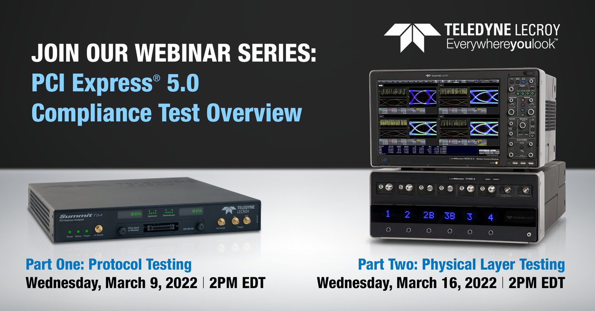
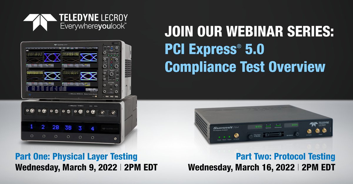
📢 Get ready for the April PCIe® 5.0 official compliance and interoperability testing with our upcoming #webinar series. Sign up here: lcry.us/3ICBmjb #PCIExpress #PCIeGen5 #HighSpeedDigital
2
16 Feb 2022
🔔 Get ready for the April PCIe® 5.0 initial compliance and interoperability testing with our upcoming #webinar series. Sign up here: lcry.us/350sepI #PCIExpress #PCIeGen5 #HighSpeedDigital
1
3
3 Feb 2022
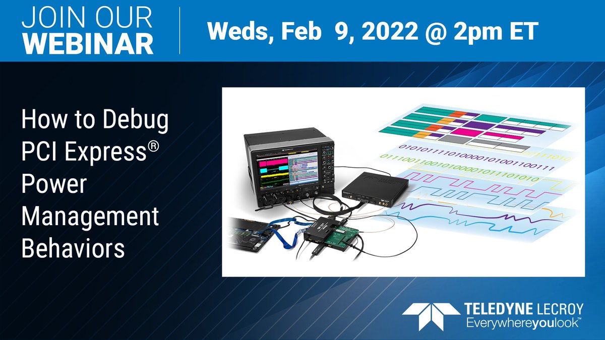
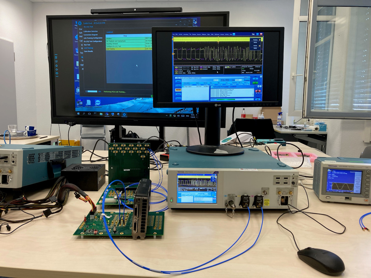
Interoperability issues can lead to finger-pointing exercises that cost money and time-to-market. Join us Feb 9 for this #webinar and learn new techniques to validate and debug #PCIe link training more! Sign up now: lcry.us/3AVbegk #HighSpeedDigital #PCIexpress
1
26 Jan 2022
#Webinar Alert - Feb 9 - learn new techniques to validate and debug #PCIe link training, power management transitions, and other protocol-directed electrical behaviors. Sign up here: lcry.us/3r21LjZ #HighSpeedDigital #PCIexpress #PCIeGen5 #PCIeGen4 #engineering

3
5

2 Nov 2021
Hear Tektronix's Dr. Ali Emsia, Ph.D. & Anritsu's Martin Storch discuss solving some of the new test and measurement transmitter and receiver challenges for #PCIe 4.0 at 16.0 GT/s and PCIE 5.0 at 32.0 GT/s. bit.ly/3mDRQPo
#HighSpeedDigital #PCIexpress #PCIeGen5 #PCIeGen4
7
21 Oct 2021
New PCIe® 5.0 CEM PHY Compliance Solution - Our QPHY-PCIE5-TX-RX software automates Base and CEM testing for PCIe 3.0, 4.0, 5.0. Learn more >> lcry.us/3neIg4G #teledynelecroy #signalintegrity #HighSpeedDigital #PCIe #PCIGen5 #PCIExpress

1
2
6 Oct 2021
Read our new technical brief and gain a clear understanding of the #PCIExpress high speed serial standard. The brief provides an overview of the current 5.0 version as well as the Tektronix solution for transmitter testing. bit.ly/2Y9NtlK #HighSpeedDigital #PCIe #PCIGen5
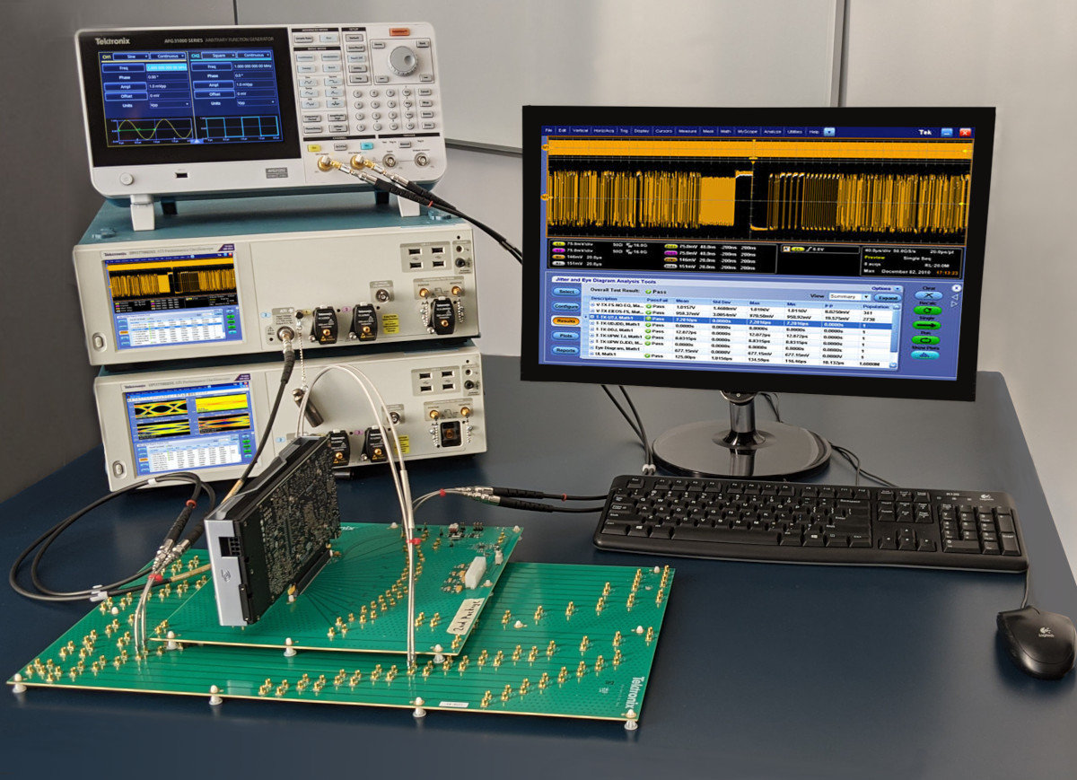
9

Moving gigabytes, terabytes and even petabytes of data have become a matter of routine for organizations across all industries. Read our newest blog!
#securenetwork #highspeeddigital #protocols #encrypted #cybersecuritytips
xsoccorp.com/post/meeting-to…
2
12
68
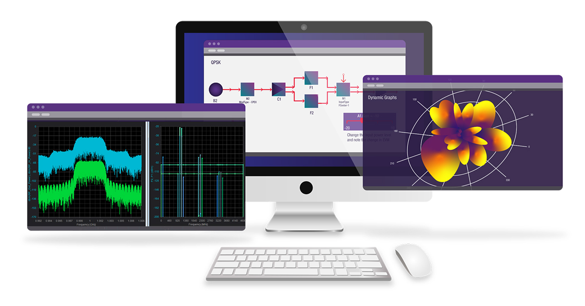
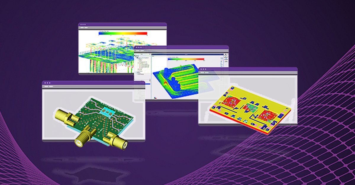
Learn about the next generation of EDA software: PathWave Design 2022. Get demos of the latest release of PathWave ADS and PathWave System Design (SystemVue).
#EDA #ElectronicDesign #DesignAutomation #CircuitDesign #HighSpeedDigital
ow.ly/zuM150EKZ1A
2
3
Announcing PathWave Design 2022. Get a first look and demo of the latest release of PathWave Advanced Design System (ADS) and PathWave System Design (SystemVue). #EDA #ElectronicDesign #DesignAutomation #CircuitDesign #HighSpeedDigital
ow.ly/YEFV50EFq7M
1
4
Announcing PathWave Design 2022. Join us to get a first look and demo of the latest release of PathWave Advanced Design System (ADS) and PathWave System Design (SystemVue). #EDA #ElectronicDesign #DesignAutomation #CircuitDesign #HighSpeedDigital
ow.ly/9irZ50EAfZ2

1
3
Keysight World 2020 India continues today with the #HighSpeedDigital track. Reserve your virtual seat now! keysight.com/zz/en/events/ke…
2
2
Join your peers at the Keysight World India #HighSpeedDigital track and stay ahead of the next speed wave. Learn to master every aspect of High Speed Digital designs across all product development stages. Register now.

1
4
Join your peers at the Keysight World 2020 #HighSpeedDigital track and stay ahead of the next speed wave. Learn to master every aspect of High Speed Digital designs across all product development stages. Register now. mintent.id/1etbs41

2
8