
Jun 12
Narrowband SIL and BiM radios provide superior RF performance for industrial wireless applications.
The NRX2B, NTX2B, NiM2B, NiM2F, NRX1B, NTX1C, NiM1B & NiM1F support programmable VHF and UHF operation with excellent range, interference rejection and reliability. radiometrix.com/family/narro…
#NarrowbandRadios #RFDesign #IndustrialIoT #Telemetry #WirelessModules

1
1
42
Jun 11
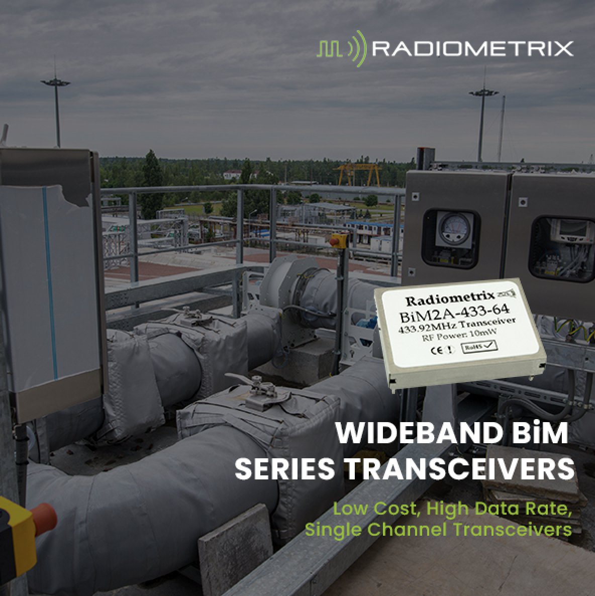
Wideband BiM series transceivers deliver LOW COST, HIGH DATA RATE, SINGLE CHANNEL TRANSCEIVERS for reliable two-way wireless communication.
Supporting 433MHz, 869MHz & 914MHz operation, the BiM2A/C/G, BiM3A/C/G & BiM3H modules provide compact, high-performance RF connectivity for industrial and embedded applications. radiometrix.com/family/wideb…
#WidebandBiMSeries #RFDesign #EmbeddedSystems #WirelessModules #IndustrialIoT
1
15

Jun 11
Design the Future of Wireless Innovation with Ansys HFSS.
To Know More Visit: arkinfo.in/ansys-simulation-…
#AnsysHFSS #Ansys #ElectromagneticSimulation #RFDesign #AntennaDesign #WirelessTechnology #5G #6G #PCBDesign #EMIEMC #SignalIntegrity #EngineeringSimulation #ElectronicsDesign

8


A CPU has billions of transistors. An RF amplifier may need only one. So why can’t the CPU do the job? The answer is not transistor count.
#RFDesign #PCB #Electronics
fastturnpcbs.com/blog/cpu-as…
1
762
Radiometrix will be exhibiting at Hardware Pioneers Max 2026 this week.
10–11 June 2026
Excel London
Stand M10
Join our team to explore the latest developments in wireless connectivity, IoT, RF engineering, and embedded system design. Discover how Radiometrix's high-performance RF modules can help accelerate your next product development project with reliable, proven wireless solutions.
Whether you're developing industrial IoT devices, telemetry systems, remote monitoring applications, or embedded wireless products, our RF specialists will be available to discuss your requirements and answer your technical questions.
Register today and visit us at Stand M10: radiometrix.com/hardware-pio…
#Wireless #IoT #RFEngineering #RFDesign #HardwareEngineering #EmbeddedSystems #HardwarePioneers #HardwarePioneersMax #WirelessConnectivity

1
23

Why Metal Film Resistors Have Inductance
In this video I discuss the inductance of modern leaded resistors - in particular the metal film resistors.
These resistors are widely used and perform well, having high accuracy and stability as well as low noise, and they are also really low cost.
The reason for the inductance is that the resistors are manufactured by depositing a thin metallic film onto a ceramic cylinder.
A helical cut is made into the metal film to extend its length and narrow its width - increasing the length and narrowing the width will increase the resistance.
The cut ensures that the resistor is of the right ohmic value. This helical cut effectively makes a coil and introduces inductance.
This may not have an effect in most instances, but for some critical circuits, especially RF designs and those that have fast edges and high clock speeds, may be upset by the inductance.
Although the levels of inductance are not high - it is worth remembering this when using these resistors and wanting to make sure everything works correctly.
Check out my video for the full details: youtu.be/XNyl0Pxas64
#resistors #metalfilm #metalfilmresistors #inductance #RFdesign #electroniccomponents
2
2
43
2,521
Are all multilayer chip inductors really ferrite-based? In RF designs, that assumption can mislead selection. Ceramic multilayer parts change the trade-offs. #RFDesign #Inductors #Electronics
fastturnpcbs.com/blog/basics…
21
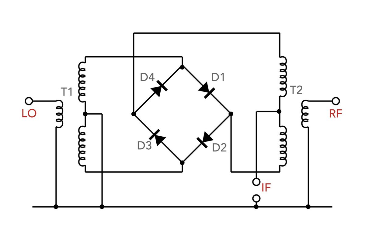
Double Balanced Mixers Explained: what they are, advantages and applications
The Double Balanced Mixer (DBM) is often considered to be the "gold standard" for high-performance frequency conversion.
Whether designing a high-end receiver or a precision spectrum analyzer, understanding why the DBM is favoured over simpler designs is key to signal integrity.
Here is a summary of why they are so critical in modern RF systems.
What Makes it "Double Balanced"?
Unlike a single balanced mixer, which only suppresses either the Local Oscillator (LO) or the Radio Frequency (RF) signal at the output, a Double Balanced Mixer suppresses both.
By using four switching elements (typically a diode ring) and two wideband transformers (baluns as the transform the unbalanced input to the balanced feed required for the switching ring), the circuit achieves a level of symmetry that cancels out even-order harmonic products.
This results in a much cleaner IF output with significantly fewer spurious signals to filter out later.
Key Advantages for Modern Design
• Superior Isolation: Because of its balanced nature, it provides high isolation between all three ports (LO-RF, LO-IF, and RF-IF). This prevents the LO signal from leaking into your antenna or overloading your IF stages.
• Increased Linearity: DBMs offer better intermodulation performance and a higher 1dB compression point compared to simpler unbalanced designs.
• Broadband Operation: Since it doesn't rely on tuned filters to separate signals, a well-designed DBM can operate over a very wide frequency range—often several octaves.
The Trade-offs
No component is perfect, and the DBM has two main requirements to keep in mind:
1. Higher LO Drive: Because the LO signal has to "switch" four diodes rather than one or two, you typically need a higher drive level (often 7dBm to 17dBm).
2. Circuit Complexity: The need for two high-quality transformers (baluns) adds to the component count and footprint, though modern MMIC versions have largely solved the space issue.
Whether you're a student getting to grips with heterodyne receivers or a seasoned engineer optimizing a front-end, the DBM remains a masterpiece of symmetrical design.
For the full technical breakdown check the link in the comments.
#RFDesign #Wireless #ElectronicsEngineering #RadioFrequency #HamRadio #HardwareDesign #MicrowaveEngineering #electronicsnotes
3
11
81
2,818
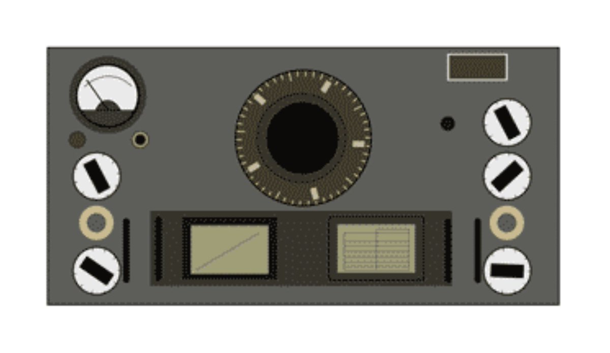
The "Hell of a Rush Order" that Changed Radio History
RF engineers often talk about the "Golden Age" of radio. But few instruments embody the transition from experimental design to professional-grade reliability quite like the National HRO.
First released in 1935, the HRO (which stood for "Hell of a Rush Order") was born from a high-stakes contract between GE and the National Radio Company.
The goal? A receiver that solved the persistent issues of image rejection and frequency stability that plagued early superheterodynes.
Why the HRO remains a masterclass in design for modern engineers:
• The Coil-Pack Solution: To avoid the signal losses and parasitic inductance associated with long leads in multi-band switches, National used pluggable coil packs. By moving the tuned circuits outside the main chassis, they achieved a level of optimization for each band that was virtually impossible with internal switching at the time.
• The Iconic Epicyclic Dial: Precise tuning was paramount. The HRO’s 500-division dial provided a high effective scale length, allowing operators to log and return to specific frequencies with a level of repeatability that was revolutionary for the 1930s.
• Operational Longevity: The fundamental design was so robust that versions of the HRO remained in professional production until 1964. It was the "workhorse" for the British Y-stations during WWII, feeding critical intercepts to the codebreakers at Bletchley Park.
As we move deeper into the era of SDR and digital signal processing, looking back at the mechanical and analog ingenuity of the HRO reminds us that "elegant solutions" often come from the most rigid constraints.
I’ve compiled a full technical breakdown of the HRO’s evolution, including the valve line-up and the circuit architecture that allowed it to cover 50 kHz to 54 MHz - yes one cool pack extended that far up.
Explore the full technical history in the link in the comments.
For more information, check the link to my website in the comments.
#RadioEngineering #RFDesign #ElectronicsHistory #EngineeringExcellence #NationalHRO #VintageTech #electronicsnotes
1
1
28
1,503
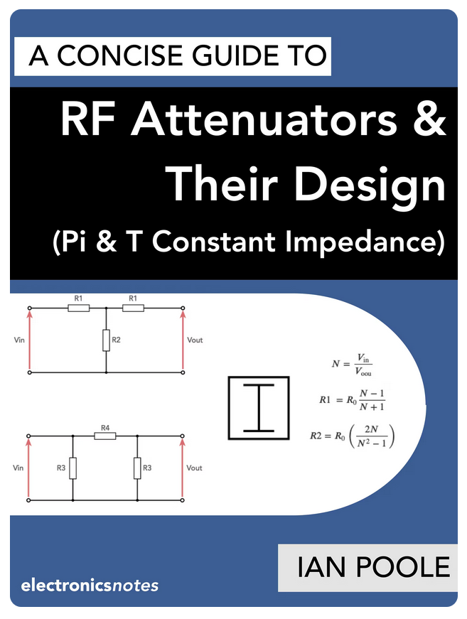
Why do we need RF attenuators? It’s not just about turning down the volume!
Whether you’re preventing receiver overload, improving impedance matching, or isolating stages in a high-frequency circuit, a well-designed attenuator is an essential tool in every RF engineer’s arsenal.
(1/4)
#RFEngineering #Electronics #WirelessTech #CircuitDesign #RadioCommunication #EngineeringTips #RFdesign
2
6
59
2,020
What is a Varactor Diode - how it works.
The key to understanding how a varactor or varicap diode works is to look at what a capacitor is and what can change the capacitance. A capacitor consists of two plates with an insulating dielectric between them.
The capacitance of the capacitor is dependent upon the area of the plates - the larger the area the greater the capacitance, and also the distance between them - the greater the distance the smaller the level of capacitance.
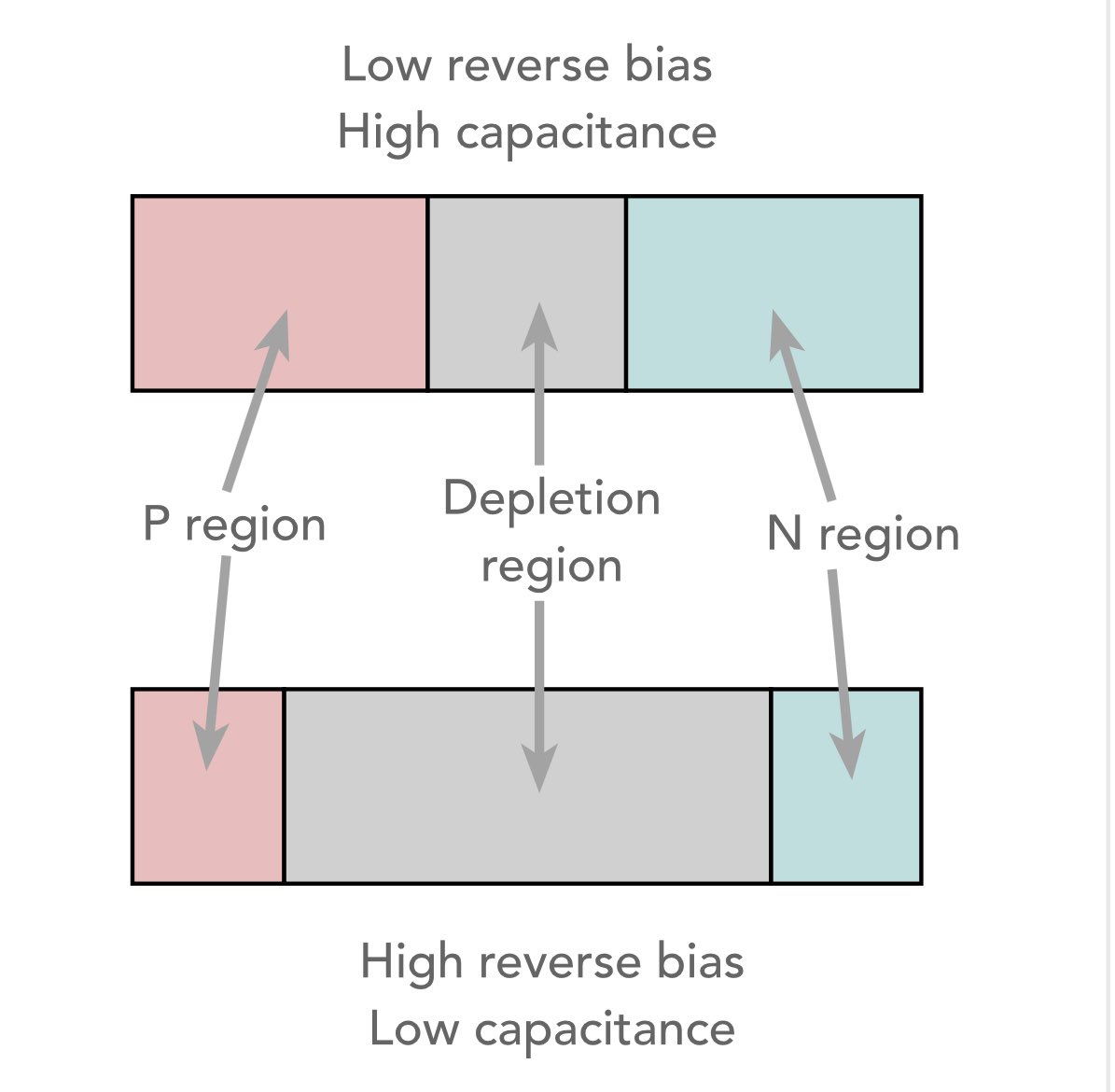
A reverse biased diode has no current flowing between the P-type area and the N-type area. The N-type region and the P-type regions can conduct electricity, and can be considered to be the two plates, and the region between them - the depletion region is the insulating dielectric. This is exactly the same as in a traditional capacitor.
As with any diode, if the reverse bias is changed so does the length of the depletion region.
If the reverse voltage on the varactor or varicap diode is increased, the depletion region of the diode increases and if the reverse voltage on varactor diode is decreased the depletion region narrows.
Therefore by changing the reverse bias on the diode it is possible to change the capacitance.
The varactor diode has a non-linear capacitance curve - the capacitance of the varactor diode is inversely proportional to the square root of the voltage across it. This means that initial changes in reverse voltage give a much greater change in capacitance, than those at higher voltages.
What are your experiences using varactor diodes?
Discover more about varactor diodes in the link in the comments.
#diode #varactor #varicap #RFdesign #RFengineering #electroniccomponents #electronicsnotes
1
7
41
1,714
Schottky Diodes Unpacked: Low Voltage Drop, High Performance
Schottky diodes may be the first form of semiconductor diode - they were the basis of the Cat’s Whisker detector used in the 1920s and also before.
The essence of the Schottky diodes may is that of a metal contact directly mounted onto the semiconductor.
The advantages of the Schottky diodes are:
* Low forward voltage drop: The low turn in voltage of silicon Schottky diodes is only about 0.3V against the 0.6 to 0.7V. This makes them ideal for power rectifiers as well as RF detectors.
* Fast switching: The very fast switching has meant they are used in many high speed circuits - they were used in the 74S and LS series logic chips and many other areas.
The downside is the lower reverse voltage and higher leakage.
Check out my video to find out all you need to know. Link is in the comments.
#diode #Schottky #Schottkydiode #rectifier #powerrectifier #RFdetector #RFdesign #electroniccomponents #electronicsnotes

1
2
43
1,723
At High Frequencies, a Capacitor is No Longer Just a Capacitor.
If you work in RF or high-speed digital circuit design, you quickly learn a harsh truth: selecting a capacitor is rarely about the capacitance value on the label. Instead, it’s about managing the component's parasitic behaviour.
In high-frequency environments, a real-world capacitor transforms into a complex RLC series circuit. If you don't account for this, your circuit will suffer from unexpected heat, power loss, or even complete signal inversion.
Here is a quick engineering guide to mastering high-frequency capacitor selection:
1. The ESR and ESL Trap
* ESR (Equivalent Series Resistance): Generates unwanted heat and power / signal loss.
* ESL (Equivalent Series Inductance): Created by physical leads and internal structures. At ultra-high frequencies, ESL dominates, causing the capacitor to behave like an inductor.
* The Rule: Choose components that stay firmly in their "capacitive region" across your target operating frequency.
2. Dielectric Matters: The RF Hierarchy
Not all ceramic capacitors are built equal. Your choice of dielectric dictates stability:
* C0G / NP0: Ultra-stable over temperature/voltage with low loss (High Q). * Use for: Tuning circuits, filters, and precision timing.
* X7R: Decently stable. *Use for:* General-purpose decoupling.
* Y5V / Z5U: High loss and massive capacitance drift with temperature. Rule of thumb: Avoid these completely in RF designs.
3. Package Geometry: Smaller is Better
In RF, physical size is a technical specification. Smaller surface-mount (SMD) packages like 0402 or 0201 inherently have less lead inductance than larger 1206 packages. Minimizing size pushes your Self-Resonant Frequency (SRF) higher, ensuring the component doesn't accidentally become inductive.
4. The Multi-Decoupling Strategy
No single capacitor can clean up a wide frequency range. Successful designs often run a hierarchy in parallel:
* Bulk low-frequency ripple ➡️ Tantalum or Electrolytic
* Mid-range noise ➡️ 0.1µF X7R
* High-frequency shunt ➡️ Small 10nF or 100pF C0G/NP0 placed as close to the IC pin as possible.
(Bonus tip: Watch out for anti-resonance humps where parallel caps interact!)
Bench Tip: Uncertain about a component’s real-world SRF? Pop the capacitor across a test fixture on a Vector Network Analyzer (VNA) and measure the S21 parameter. The bottom of the resulting "V" curve marks your exact self-resonance point.
What are your go-to layout tricks for minimizing loop inductance in high-speed designs? Let’s discuss in the comments! 👇
Read the full guide in the link in the comments.
#HardwareEngineering #RFDesign #PCBDesign #CircuitDesign #ElectronicsEngineering #HighSpeedDigital #electroniccomponents #electronicsnotes

5
24
194
9,467

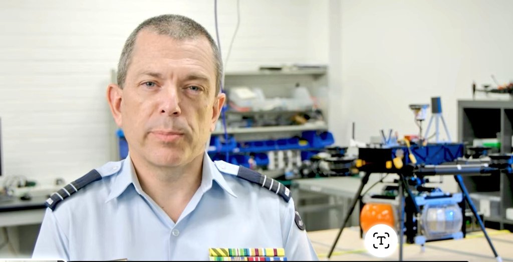
Our team ran a famil session for #CamelTrain this week with a stack.of our stakeholders! Great job Pat and the #RFDesign team!
@AusAirForce @AAUS_Live @TheCentralBlue @DefenceAust @AustralianArmy


All 🇦🇺!
🇦🇺 designed, built and @CASABriefing type certified: #Jabiru 400
🇦🇺 engineering and comms from #RFDesign Pty Ltd
🇦🇺 optical detect and avoid from @revaero_au
🇦🇺 flight controller from @CubePilot
🇦🇺 radar detect and avoid from @MissSysPtyLtd
youtu.be/mB3HKoGk8zo
1
1
4
359
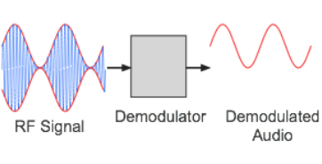
HOW to demodulate amplitude modulated signals
Demodulation is a key process in the reception of any amplitude modulated signals whether used for broadcast or two way radio communication systems.
Demodulation is the process by which the original information bearing signal, i.e. the modulation is extracted from the incoming overall received signal.
The process of demodulation for signals using amplitude modulation can be achieved in a number of different techniques, each of which has its own advantage.
The demodulator is the circuit, or for a software defined radio, the software that is used to recover the information content from the overall incoming modulated signal.
AM demodulators are found in many items of radio equipment: broadcast receivers, professional radio communication equipment, walkie talkies - AM is still used for air-band radio communications.
The terms detection and demodulation are often used when referring to the overall demodulation process. Essentially the terms describe the same process, and the same circuits.
As the name indicates the demodulation process is the opposite of modulation, where a signal such as an audio signal is applied to a carrier.
In the demodulation process the audio or other signal carried by amplitude variations on the carrier is extracted from the overall signal to appear at the output.
As the most common use for amplitude modulation is for audio applications, the most common output is the audio. This may be broadcast entertainment for broadcast reception, and for two way radio communications, it is often used for land communications for aeronautical associated applications - often within walkie talkies.
There are three main types of circuit used for AM demodulation:
- The diode envelope detector. This basically rectifies the signal and allows one half of it through. This half contains the modulation in a format that can be applied to further audio or other stages.
- Product detector. This basically uses a beat frequency oscillator tuned to exactly the same frequency as the carrier. The BFO signal mixes wit the incoming AM signal and one of the mix products is the required modulation. The disadvantage of this is that the receiver has to be tuned so that the BFO is on exactly the same frequency as the carrier, otherwise the result is unsatisfactory - beat note with the carrier and audio on wrong frequency!
- Synchronous detector. This is effectively a development of the BFO approach, but it uses one of a variety of means to develop the beat frequency signal on exactly the same frequency as the carrier. This can be achieved by using a PLL locked to the carrier, but one of the most convenient methods is to just limit the incoming signal to remove all modulation and hence produce the carrier.
Check out more: electronics-notes.com/articl…
#AM #amplitudemodulation #demodulation #radios #RFdesign #radiotechnology #RFdesign #electronicsnotes
1
30
903
Understand Quartz Crystal Ageing: long term stability & accuracy
The resonant frequency of quartz crystal resonators moves by a small amount over time in a process called ageing.
Quartz crystal ageing is caused by many different factors.
Differnet crystals age at different rates and this can be attributed to a number of factors: some in the manufacturing process and some by the way they are used.
- Crystal surface change
- Crystal lattice contamination
- Thermal effects
- Wire fatigue
- Frictional wear
- Drive level
The level of ageing can be minimised in a number of ways both in manufacture and in use:
- Reducing ageing in manufacture: During manufacture they should be encapsulated in an inert gas environment, the ensuring should have a good seal so that other gases do not enter. Also the final stages of the preparation of the crystal blank must be prepared as finely as possible. Rather than lapping the blank to bring it to the right dimensions, chemical etching is used. In this way the minimum disruption is caused to the crystal lattice, and this reduces the ingress of contaminants over time that will cause ageing.
- Reducing ageing in use: The design of the circuit in which the crystal will be used also has an effect. By keeping the drive levels low again the crystal ageing will be less.
As expected the rates of change of the crystal frequency vary with the time after manufacture.
The maximum rate of change of frequency occurs immediately after manufacture and decays thereafter.
As a guide it is found that it is fastest within the first 45 days of operation. Even so there is always some degree of ageing throughout the life of the crystal.
In view of the fact that the greatest rate of change is immediately after manufacture, high tolerance items are often run for some time before being shipped. In very high tolerance items this may extend to a few months of operation.
For more information check out the link in the comments.
#quartzcrystals #ageing #frequencystandard #ekectronics #HardwareEngineering #HardwareDesign #RFdesign #electronicsnotes

1
7
37
1,789
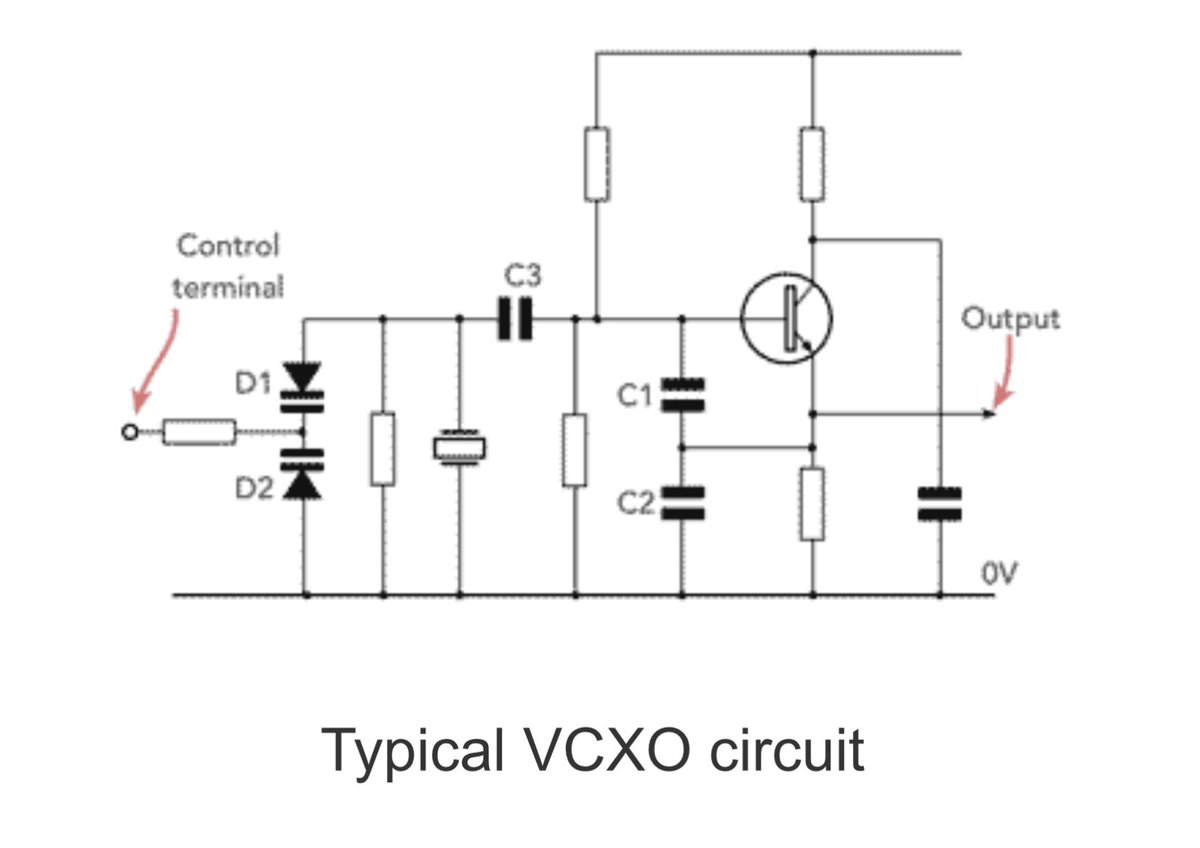
What is a VCXO? Where can I use them in my circuit designs?
A Voltage Controlled Crystal Oscillator (VCXO) combines the high stability of a quartz crystal with the flexibility of a voltage-controlled adjustment. It allows you to "pull" or trim the frequency by a small amount using an external control voltage.
#Electronics #engineering #electroniccomponents #crystaloscillators #vcxo #voltagecontrolledcrystaloscillator #electronicsnotes #RFDesign #Oscillators
1
14
87
3,472
Ceramic resonators and filters: essential elements for modern RF design
These resonators and filters offer a perfect balance between the high performance of quartz crystals and the low cost of LC circuits for many designs.
Based on the insights from Electronics Notes, here is a breakdown of why these components are essential for your next radio frequency project.
Ceramic Resonators & Filters: The Mid-Range Powerhouse
When designing RF or IF (Intermediate Frequency) stages, engineers often face a dilemma: choose the high-precision but costly quartz crystal, or the cheap but less stable LC filter? Ceramic technology fills that gap perfectly.
1. Why Ceramics?
Ceramic filters utilize piezoelectric elements (often PZT - lead zirconium titanate) to convert electrical signals into mechanical vibrations.
• Cost-Effective: Significantly cheaper than quartz for mass production.
• Compact: Available in both leaded and SMD formats, ideal for space-constrained designs.
• Performance: With Q factors ranging from 500 to over 10,000, they offer much sharper selectivity than traditional LC circuits.
2. Resonator vs. Filter: Know the Difference
• Ceramic Resonator (2-Pin): The ceramic equivalent of a single crystal. It’s a two-terminal component used in oscillators where extreme precision isn't mandatory but cost is.
• Ceramic Filter (3 or 4-Pin): These are integrated bandpass solutions. A 3-pin setup typically includes Input, Output, and a common Ground, effectively replacing multiple LC transformers with a single component.
3. Frequency Versatility
While they were once limited to lower frequencies (like the classic 10.7 MHz IF for FM radio), modern ceramics now reach into the UHF range and beyond. Depending on the frequency, they operate in different vibration modes:
• Flexural Mode: Below 50kHz
• Area Expansion Mode: 100kHz – 2MHz
• Thickness Shear/Expander Mode: 1MHz – 25MHz
4. Pro-Tip for Designers
Remember that ceramic filters are insulators—they do not provide a DC path. When integrating them into a transistor-based IF amplifier, ensure your circuit provides external bias and source current. Additionally, matching the source and load impedance is critical to achieving the specified bandwidth and ripple performance.
Are you using ceramic filters in your latest RF designs, or do you still prefer the precision of quartz? Let’s discuss in the comments!
For more information check out the link in the comments.
#ElectronicsEngineering #RFDesign #electroniccomponents #CircuitDesign #WirelessTech #CeramicResonators #HardwareEngineering #electronicsnotes

1
10
46
2,269
All 🇦🇺!
🇦🇺 designed, built and @CASABriefing type certified: #Jabiru 400
🇦🇺 engineering and comms from #RFDesign Pty Ltd
🇦🇺 optical detect and avoid from @revaero_au
🇦🇺 flight controller from @CubePilot
🇦🇺 radar detect and avoid from @MissSysPtyLtd
youtu.be/mB3HKoGk8zo
Want to learn about how #CamelTrain 🇦🇺 autonomous aerial logistics is developing? Come say G'day at the @AusAirForce #ASPCon26 Air and Space Power Conference!
Camel Train is being engineered by 🇦🇺 #RFDesign Pty Ltd ...
2
2
20
961